Method and device for implementing the multi-wave bundle intelligent antenna with the directional antenna

A technology for directional antennas and smart antennas, which is applied in the direction of independent non-interactive antenna combinations, antennas, and selection devices, can solve the problems of failure of adaptive antenna null suppression, large amount of calculation for signal processing and beamforming, and unsuitability for mobile applications. Communication system and other issues, to achieve the effect of increasing the number of users and base station coverage, reducing electromagnetic pollution, and improving spectrum utilization

Inactive Publication Date: 2007-10-17
LANZHOU UNIV ELECTRONICS TECH DEV APPL RES INST
View PDF0 Cites 59 Cited by
  • Summary
  • Abstract
  • Description
  • Claims
  • Application Information

AI Technical Summary

Problems solved by technology

[0008] Adaptive beam smart antennas and pre-multi-beam smart antennas have existed for many years, but there are still big obstacles on the road to practical application
[0009] First, parameter estimation complexity and latency are a big problem in array system design
Adaptive array antennas and pre-multi-beam smart antenna weights are formed through iterative algorithms. The signal processing and beamforming calculations are huge, and there is a large delay expansion. The positioning and response speed will be limited, and it is difficult to achieve fast tracking.
[0010] Second, signal cancellation caused by multi-channel and correlated signals is also an important issue in adaptive array signal processing algorithms
[0011] Third, interference suppression is limited, and the ability to increase channel capacity is low
In the actual channel of mobile communication, the complex communication environment makes the received signal contain a large number of multipath signals and co-channel interference of the target user itself. The null trap formed by the array antenna through the antenna synthesis technology cannot exceed the number of unit antennas. However, the number of multipath and interference is far greater than the number of array antenna units, and because the omnidirectionality of the unit antenna of the adaptive smart antenna and the pre-multi-beam smart antenna makes the interference spread in all directions around, the adaptive algorithm cannot be formed through the limited array elements. Therefore, in this complex multipath propagation environment, the nulling suppression effect of the adaptive antenna has partially failed, and the interference in the main lobe cannot be suppressed.
So it is not the most effective way to increase channel capacity, the ability of distributed antenna, multi-beam antenna or sector antenna to increase channel capacity is far greater than that of adaptive smart antenna
[0012] Fourth, poor compatibility and high construction costs
Adaptive smart antennas need to use powerful and expensive processors in antenna design in order to improve airspace beamforming and time domain equalization, and it is difficult to be compatible with existing base stations and cannot be applied to existing mobile communication systems

Method used


Image

  • Method and device for implementing the multi-wave bundle intelligent antenna with the directional antenna
  • Method and device for implementing the multi-wave bundle intelligent antenna with the directional antenna
  • Method and device for implementing the multi-wave bundle intelligent antenna with the directional antenna

Examples


Embodiment Construction

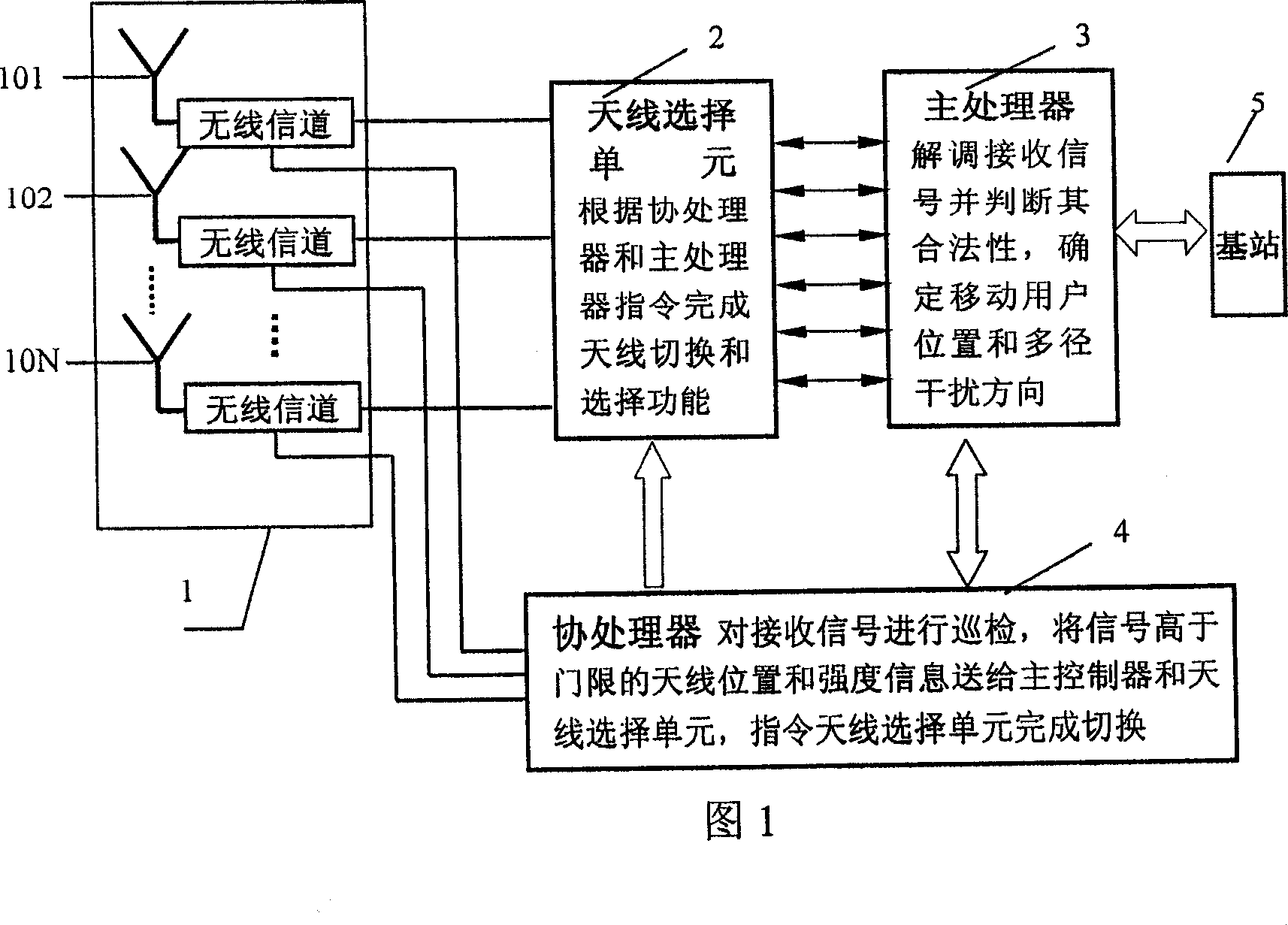
[0052] The method and device of the present invention will be further described below in conjunction with the embodiments and accompanying drawings.

[0053] Referring to Fig. 1, the basic structure of the multi-beam smart antenna that realizes with directional antenna of the present invention is shown among the figure, comprise and form antenna array 1 by mutually independent N face directional antenna 101,102...10N, main processor 3, cooperative The processor unit 4 and the antenna selection unit 2 are four parts; the N-face directional antennas 101, 102...10N are respectively connected to the input terminals of the coprocessor 4, and the output terminals of the coprocessor 4 are connected to the antenna selection unit 2 and the main processor 3 respectively. The output end of the main processor 3 is connected with the antenna selection unit 2 and the base station 5 respectively.

[0054] The specific number and types of directional antennas are determined according to the e...


PUM


Abstract

A method and an apparatus for realizing a multibeam smart antenna by directional antennas in a mobile communication system, are provided. The method comprises performing space division on a base station service region by N directional antennas independent with one another to divide the base station service region into N cells, each cell satisfying a perdetermined electromagnetic radialization request; composing a delamination multibeam array by the N directional antennas based on the region to be covered by the base station, the directional antenna adjusting direction of the beam in advance to realize space division multiple access, the antenna for performing transmission and receiving of signals are controlled by a main processor unit, auxiliary processors and an antenna selection unit to position and track a mobile user. The apparatus includes a delamination antenna array composed of N directional antennas independent with one another, the antenna selection unit, auxiliary processors, a main processor; wherein the N directional antennas are connected with input ends of the auxiliary processors respectively, the auxiliary processors are connected with the antenna selection unit and the main processor respectively, the main processor is connected with the antenna selection unit and the base station. The invention has a high communication capacity and immunity.

Description

technical field [0001] The present invention relates to a wireless communication system, in particular to a method and device for realizing a multi-beam smart antenna by using a directional antenna in a cellular mobile communication system. Background technique [0002] In a wireless communication system, a signal is propagated between a user equipment and a base station through a wireless channel. Since the transmission conditions of wireless channels are worse than those of wired channels, there are many unfavorable factors such as fading, multipath and co-channel interference, so the signal transmission, reception and processing methods of wireless communication systems are a decisive factor that directly affects system performance. [0003] With the rapid development of communication technology, people's demand for network communication is also increasing, especially with the arrival of the third generation mobile communication system 3G (Third Generation) communication ...

Claims


Application Information

Patent Timeline
Patent Type & Authority Applications(China)
IPC IPC(8): H04Q7/36H01Q21/28H01Q13/00H01Q19/10H04B7/04H04B7/10H04W16/28
Inventor 张金生韩贵杰李柏年常蓬彬
Owner LANZHOU UNIV ELECTRONICS TECH DEV APPL RES INST
Why Eureka
Try Eureka