Testing device and method for measuring laser range finder transmitting and receiving axis matching degree

A distance measuring system and laser measuring technology, which are applied to measuring devices, radio wave measuring systems, electromagnetic wave re-radiation and other directions, can solve problems such as the inability to detect the registration of the sending and receiving axes of the system, and achieve simple structure, high precision and low cost. Effect

Inactive Publication Date: 2007-10-24
SHANGHAI INST OF TECHNICAL PHYSICS - CHINESE ACAD OF SCI
View PDF0 Cites 22 Cited by
  • Summary
  • Abstract
  • Description
  • Claims
  • Application Information

AI Technical Summary

Problems solved by technology

However, after the assembly of the whole machine is completed, the system output is an electrical signal,

Method used


Image

  • Testing device and method for measuring laser range finder transmitting and receiving axis matching degree
  • Testing device and method for measuring laser range finder transmitting and receiving axis matching degree

Examples


Embodiment Construction

[0023] Below according to Fig. 1, Fig. 2 provide a better embodiment of the present invention and elaborate:

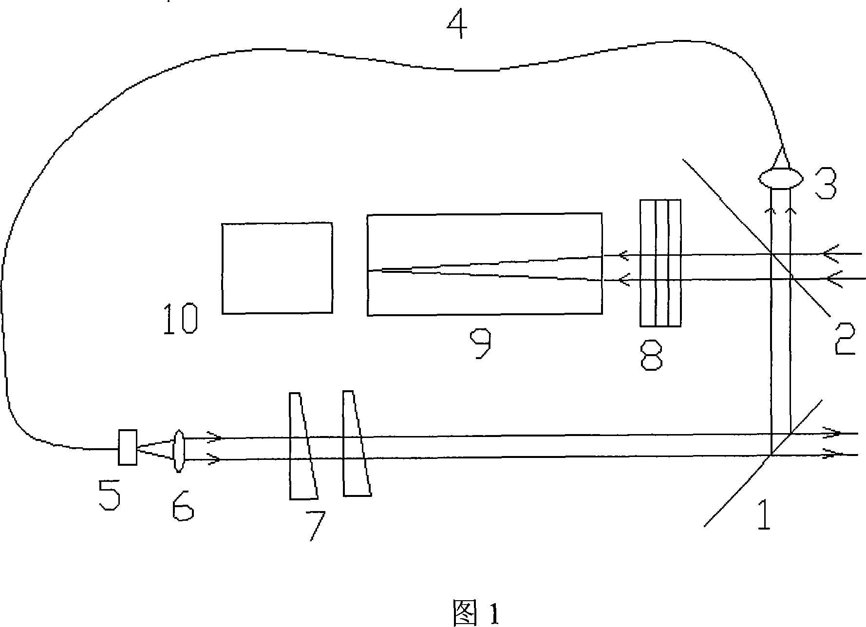
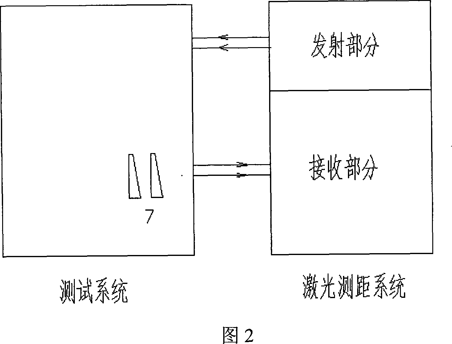
[0024] FIG. 1 is a schematic diagram of a testing device of the present invention, which is composed of a beam deflector, a collimator 9 , a camera 10 , an analog echo generator and a beam angle fine-tuner 7 . The beam turning mirror is composed of a first half mirror 1 and a second half mirror 2 with an included angle of 90°. The laser-fiber coupler 3, the multimode fiber 4, the adjustable fiber attenuator 5, and the fiber collimator 6 together constitute an analog echo generator. The optical fiber 4 adopts 62.5um / 125um multimode optical fiber, and the length can be adjusted according to the needs of the instrument under test. The length in this embodiment is 5km; the adjustable optical fiber attenuator 5 adopts FC-flange type. The beam angle fine-tuner 7 is composed of two pairs of optical wedges, which are respectively installed on two turntables for horizontal an...


PUM


Abstract

The invention discloses a device for testing the registration of receiving shaft and emitting shaft of a laser ranging system, wherein the device comprises a beam folder, a collimator, an analogue echo generator, and a beam angle micro adjuster. The analogue echo generator is composed of a fiber couple, a multimode fiber, a fiber collimator, and an adjustable fiber attenuator. Th method uses the collimator and the beam angle micro adjuster to adjust a reference beam and an analogue echo parallel to accurately mark the initial position of the analogue echo light, adjusts the beam angle micro adjuster, to watch the change of the output signal of the receiving part of the object system to obtain the adjusted angle value, to be compared with the angle value of the initial position to obtain the horizontal and vertical bias of the emitting shaft and the receiving shaft of the laser ranging system. The invention has the advantages that the invention directly uses the laser of the object system to couple, without additional lasers, with simple structure, and combines the beam angle and the output signal of the object system, to improve the reliability and accuracy of the test result.

Description

technical field [0001] The invention relates to a performance test of a laser distance measuring system, in particular to a test device and method for detecting the registration degree of a transmitting axis and a receiving axis of the laser ranging system after installation. Background technique [0002] The basic working principle of the laser ranging system is: by measuring the time difference between emitting the laser and receiving the laser echo to obtain the distance traveled by the light during the period, and then obtain the distance value. [0003] With the development of laser technology and echo detection technology, the distance that can be measured by laser ranging is getting farther and farther. Not only can it be carried on the aircraft platform, but more and more countries are carrying it on the spaceborne platform. According to the measured distance data and corresponding processing, information such as the shape, surface reflectivity and height of the mea...

Claims


Application Information

Patent Timeline
IPC IPC(8): G01S17/08
Inventor 狄慧鸽方抗美舒嵘王建宇
Owner SHANGHAI INST OF TECHNICAL PHYSICS - CHINESE ACAD OF SCI
Why Eureka
Try Eureka