Energy-saving control device for beam pumping unit

An energy-saving control and beam-type technology, which is applied in the direction of circuit devices, emergency protection circuit devices, emergency protection circuit devices for limiting overcurrent/overvoltage, etc. Low power factor of the system, excessive loss of low-voltage distribution lines, etc., achieve the effect of automatically tracking the change of reactive power, saving active power, and increasing the excitation potential

Inactive Publication Date: 2007-10-24
北京天安顺达科技发展有限责任公司
View PDF2 Cites 3 Cited by
  • Summary
  • Abstract
  • Description
  • Claims
  • Application Information

AI Technical Summary

Problems solved by technology

Due to the above reasons, the actual load rate of the pumping units is generally low, and the load rate of most of the pumping units is between 20% and 30%, forming the phenomenon of "big horses and small carts"
When the motor is in light-load operation, its efficiency and power factor are low. The power factor of the oil field power distribution system has been low for a long time, and the loss of the low-voltage distribution line is too large. motor, it is advisable to adopt the method of in-situ reactive power compensation of the motor
However, most of the existing reactive power compensation devices use the power factor that changes rapidly when the pumping unit is running as a signal, and the devices without exception adopt a strategy of delay switching, so they cannot play their due role
[0009] There are some methods in the prior art to solve the above problems, such as the beam pumping unit pressure regulation and reactive power compensation control device mentioned in CN2702083Y, and the beam pumping unit asynchronous motor mentioned in CN1808887A energy-saving control method and control device, but the specific implementation of these schemes is relatively complicated, and cannot improve the comprehensive energy-saving of the pumping unit

Method used


Image

  • Energy-saving control device for beam pumping unit
  • Energy-saving control device for beam pumping unit
  • Energy-saving control device for beam pumping unit

Examples


Embodiment Construction

[0039] The following examples are used to illustrate the present invention, but not to limit the scope of the present invention.

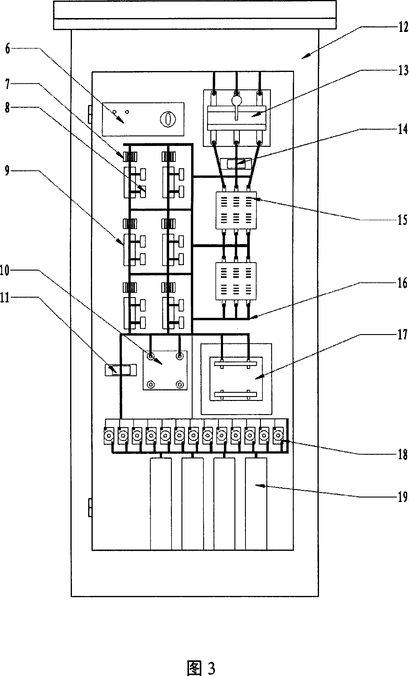
[0040]As shown in Fig. 3, Fig. 3 is a schematic diagram of the internal structure of the energy saving control device of the present invention. The energy-saving control device according to the present invention includes a thyristor switching capacitor and its controller. A triangular compensation circuit is connected in parallel at the outlet end of the motor. There are three components of a thyristor, a reactor and a compensation capacitor on each side of the triangle. The thyristor is composed of The controller detects the current state of the outlet terminal of the motor to control whether it is switched on or not. Specific devices include controller 6, SCR driver 7, voltage equalizing resistor 8, thyristor 9, transformer 10, current transformer A11, cabinet 12, circuit breaker 13, current transformer B14, AC contactor 15, primary power distributio...


PUM


Abstract

The related motor saving-energy control device for . 14kV-series walking-beam-type pumping unit comprises a TSC that uses a thyristor capacitor to automatic fast switch compensation on the motor outlet with motor reactive current Iq as signal. This invention reduces loss greatly, and achieves purpose for saving both reactive and active power.

Description

Technical field [0001] The invention relates to the field of petroleum extraction machinery, in particular to an energy-saving control device for a beam pumping unit. Background technique [0002] The beam pumping unit is a mining machine widely used in oilfield systems. It has a simple structure and high reliability; but it has a large starting torque and a poor balance effect. The load changes greatly within one stroke. When the pumping conditions change , The load also changes, which determines that a certain power capacity is bound to remain when selecting the pumping unit. This results in low efficiency, low power factor, and large additional power loss. At present, the total installed capacity of pumping unit motors in my country is about 3,500 MW, and the annual power consumption exceeds 10 billion kW·h. The operating efficiency of the pumping unit is low, and the annual energy saving potential can reach several billion kW·h. [0003] The beam pumping units commonly used i...

Claims


Application Information

Patent Timeline
Patent Type & Authority Applications(China)
IPC IPC(8): H02J3/18H02P23/02H02H9/04
CPCY02E40/12Y02E40/10
Inventor 刘文军谢富春
Owner 北京天安顺达科技发展有限责任公司
Why Eureka
Try Eureka