

Oxygen-enriched combustion radiant tube heaters
A radiant tube heater and oxygen-enriched combustion technology, applied in burners, gas fuel burners, combustion methods, etc., can solve the problems of poor flue gas waste heat recovery and thermal efficiency problems, and improve stability and reliability. , Improve the heat utilization rate and improve the effect of heat exchange
- Summary
- Abstract
- Description
- Claims
- Application Information
AI Technical Summary
Problems solved by technology
Method used
Image

Examples
Embodiment Construction
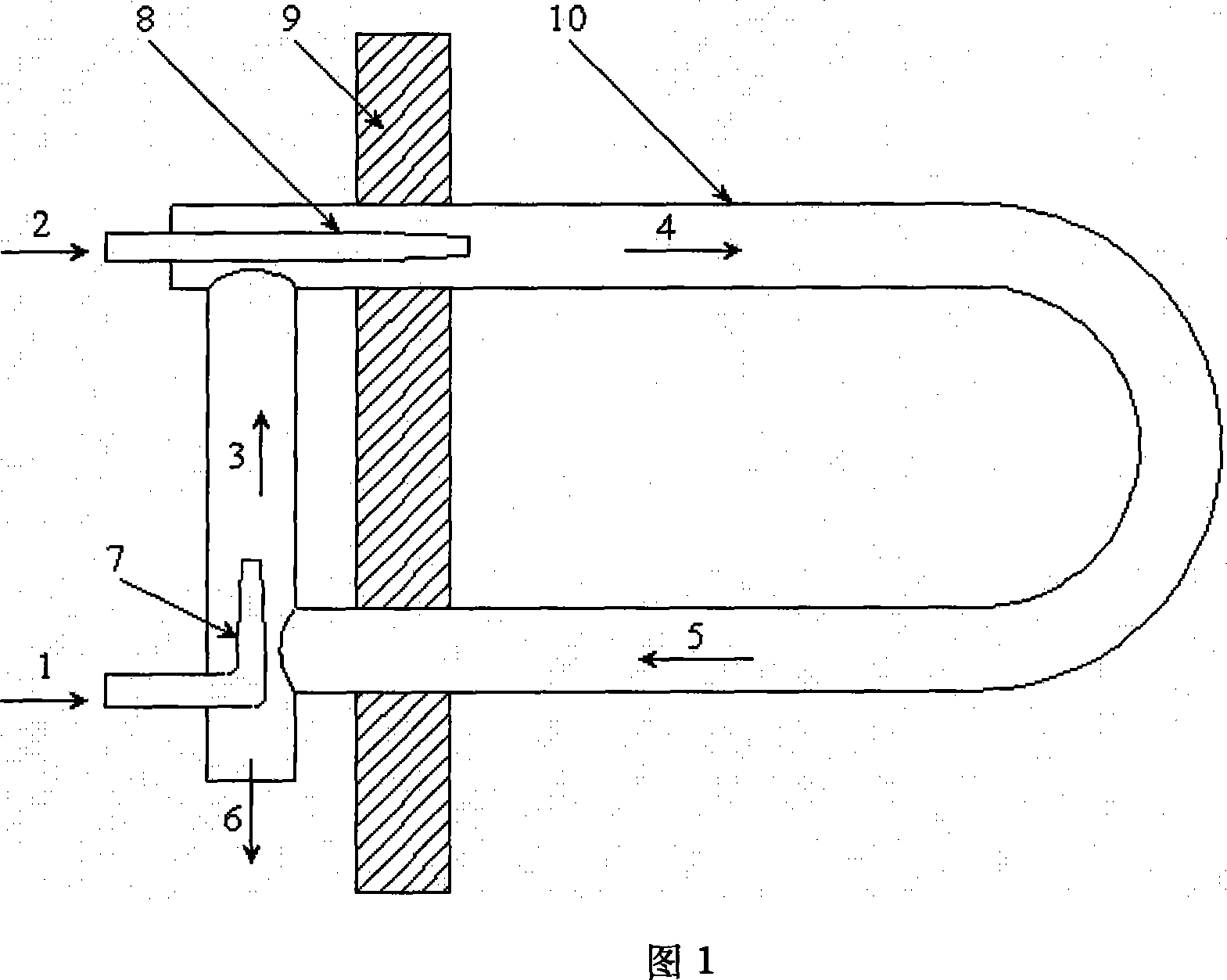
[0013] 1. The ejector is located in the outer radiant tube system structure of the furnace wall. It consists of oxygen or oxygen-enriched air 1, fuel 2, a mixture of oxygen or oxygen-enriched air and combustion flue gas 3, combustion gas 4, flue gas in the radiant tube 5, The flue gas 6 discharged from the radiant tube, the flue gas ejector 7, the burner 8, the furnace wall 9, and the radiant tube 10 are composed. The ejector is located on the outside of the furnace wall. Although it is easy to install, it has certain radiation and convective heat transfer to the environment, which is not good for the environment outside the furnace.
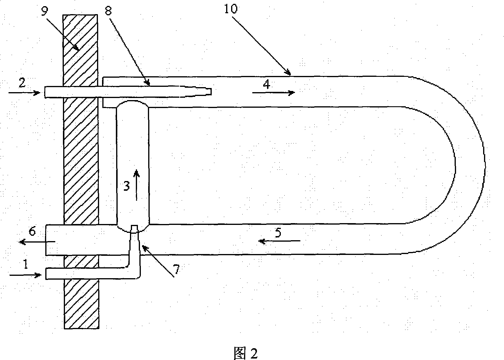
[0014] 2. The ejector is located in the inner radiant tube system structure of the furnace wall, which consists of oxygen or oxygen-enriched air 1, fuel 2, mixed gas 3 of oxygen or oxygen-enriched air and combustion flue gas, combustion gas 4, flue gas in the radiant tube 5, The flue gas 6 discharged from the radiant tube, the flue gas ejector 7...
PUM
 Abstract
Description
Claims
Application Information