Current converter test circuit

A test circuit and converter technology, applied in the field of converters, can solve the problems of high cost of test equipment, high maintenance cost, complex system, etc., so as to reduce the cost of test and test equipment, reduce complexity and floor space , to avoid the effect of mechanical noise

Active Publication Date: 2007-11-14
ZHUZHOU CSR TIMES ELECTRIC CO LTD
View PDF0 Cites 16 Cited by
  • Summary
  • Abstract
  • Description
  • Claims
  • Application Information

AI Technical Summary

Problems solved by technology

Among them, the method shown in Figure 1 needs to set up several groups of motors, so that it has problems such as complex system, large floor space, and high cost of test equipment; at the same time, the transmission equipment is easy to wear, and the maintenance cost is high; Continuous rotation, loud mechanical noise
In the method shown in Figure 2, because all the test power is consumed through the resistance, the electric energy cannot be recovered, and the energy loss is huge; because this method needs to configure high-power heat dissipation equipment for the load, the cost increases. When using heat dissipation equipment such as fans, it will also generate noise

Method used


Image

  • Current converter test circuit
  • Current converter test circuit
  • Current converter test circuit

Examples


Embodiment Construction

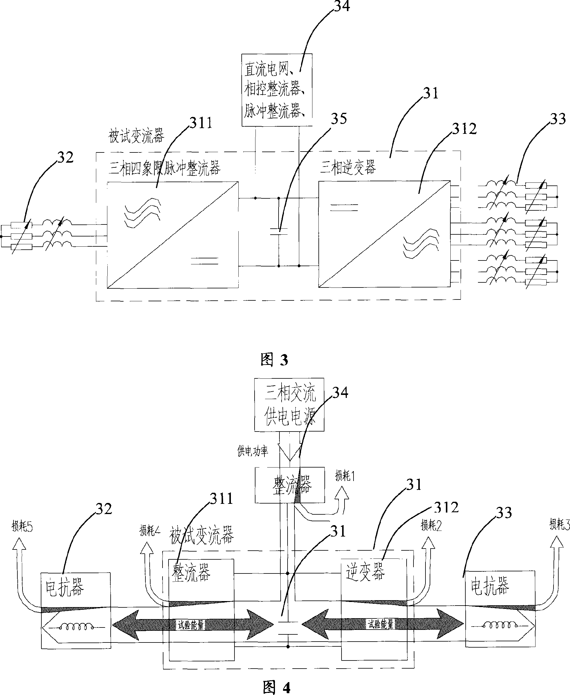
[0036] Please refer to FIG. 3 , which shows the circuit principle of the converter test circuit provided by the first embodiment of the present invention.

[0037] In the experimental circuit provided in this embodiment, the tested converter 31 includes a rectifier 311 and an inverter 312 . The rectifier 311 is a three-phase four-quadrant pulse rectifier; the inverter 312 is a three-phase inverter and can provide multiple output terminals.

[0038] The output end of the rectifier 311 is connected to the input end of the inverter 312 through a DC bus. An energy storage capacitor 35 is connected in parallel between the positive and negative poles of the DC bus. The input end of the rectifier 311 is connected to a high inductive load 32 , and the output end of the inverter 312 is connected to a high inductive load 33 . The high inductance loads 32 and 33 can be one or more groups of three-phase loads, each phase is a series circuit of adjustable or fixed inductance and adjustab...


PUM


Abstract

This invention discloses a converter test circuit. The test converter work in the inverter of 'DC - single-phase AC or three-phase AC'. That is to transform DC into single-phase or three-phase AC, the testes converter DC-DC is connected to power supply, and there is a the DC power supply is a energy storage capacitor between the negative and positive, the AC end is connected to high inductive load. In test, described high inductive load through the pulse width modulation control of the converter, achieve the energy cycle between energy storage capacitor through reactive power. Adopt the test circuit, as long as the appropriate control of the converter can achieve converter work with the actual work in the same current and power conditions to get equal effective test data of existing technology, but the actual energy loss was very small.

Description

technical field [0001] The invention relates to the converter technology, in particular to a test circuit of the converter. Background technique [0002] In various motor drive occasions, high-power converters are widely used. These converters are used to provide drive power to the motor. During the conversion process, the power supply voltage provided by the power supply network is converted into a power supply voltage of appropriate voltage and frequency, which is provided to the motor. [0003] For high-power converters in the above-mentioned applications, it is necessary to test the working conditions of the converter through test methods. In the prior art, a test circuit as shown in Fig. 1a-1c or Fig. 2a-2c is adopted. [0004] The three test circuits shown in Fig. 1a-1c respectively adopt the same test method for different types of converters. Their common feature is that an asynchronous motor is connected to the output end of the converter as a load. After the async...

Claims


Application Information

Patent Timeline
Patent Type & Authority Applications(China)
IPC IPC(8): G01R31/40G01R31/42H02M5/40H02M5/44
Inventor 冯江华陈高华丁荣军杨文昭
Owner ZHUZHOU CSR TIMES ELECTRIC CO LTD
Why Eureka
Try Eureka