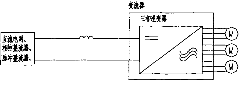
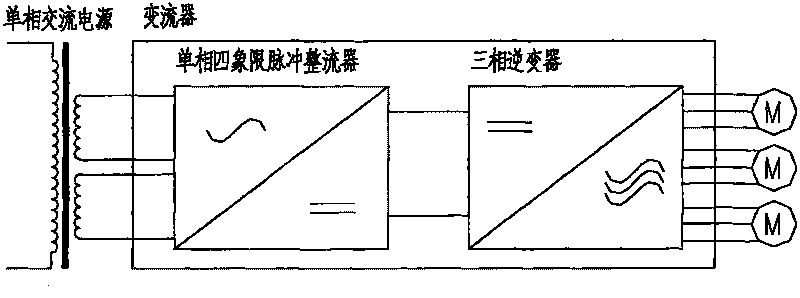
Current converter test circuit
A test circuit and converter technology, applied in the field of converters, can solve the problems of high cost of test equipment, high maintenance cost, complex system, etc., to reduce test cost and test equipment cost, reduce complexity and occupy an area , to avoid the effect of mechanical noise
- Summary
- Abstract
- Description
- Claims
- Application Information
AI Technical Summary
Problems solved by technology
Method used
Image
Examples
Embodiment Construction
[0036] Please see image 3 , which shows the circuit principle of the converter test circuit provided by the first embodiment of the present invention.
[0037] In the experimental circuit provided in this embodiment, the tested converter 31 includes a rectifier 311 and an inverter 312 . The rectifier 311 is a three-phase four-quadrant pulse rectifier; the inverter 312 is a three-phase inverter and can provide multiple output terminals.
[0038] The output end of the rectifier 311 is connected to the input end of the inverter 312 through a DC bus. An energy storage capacitor 35 is connected in parallel between the positive and negative poles of the DC bus. The input end of the rectifier 311 is connected to a high inductive load 32 , and the output end of the inverter 312 is connected to a high inductive load 33 . The high inductance loads 32 and 33 can be one or more groups of three-phase loads, each phase is a series circuit of adjustable or fixed inductance and adjustable...
PUM
 Abstract
Description
Claims
Application Information
 - R&D
- Intellectual Property
- Life Sciences
- Materials
- Tech Scout
- Unparalleled Data Quality
- Higher Quality Content
- 60% Fewer Hallucinations
Browse by: Latest US Patents, China's latest patents, Technical Efficacy Thesaurus, Application Domain, Technology Topic, Popular Technical Reports.
© 2025 PatSnap. All rights reserved.Legal|Privacy policy|Modern Slavery Act Transparency Statement|Sitemap|About US| Contact US: help@patsnap.com


