Composite roller of high-performance binded hard alloy

A technology of cemented carbide and composite rolls, applied in the direction of rolls, metal rolling, metal rolling, etc., can solve the problems of limited bonding strength rolling torque, low ability to transmit rolling torque, limited bonding area, etc.

Inactive Publication Date: 2007-11-21
ZHEJIANG METALLURGICAL RES INST
View PDF7 Cites 6 Cited by
  • Summary
  • Abstract
  • Description
  • Claims
  • Application Information

AI Technical Summary

Problems solved by technology

Although these metallurgical composite methods have the advantages of high bonding strength of the inner and outer rings, good temperature resistance, and can reduce the cost of the cemented carbide, the process is complicated, and due to the high temperature manufacturing, there may also be a decrease in the performance of the cemented carbide, and the thermal expansion of the bonding layer. Various stress defects caused by different rates
[0005] Another composite process is chemical bonding process, but there are some shortcomings in the existing bonding composite process, such as CN1513617 "tungsten carbide composite roll" discloses that the roll shaft containing the protruding part is directly bonded with the cemented carbide roll ring Composite roll technology; CN1389320 "a kind of manufacturing process of composite bonded hard alloy roll" discloses the roll shaft processed by electrochemical film formation and the cemented carbide roll ring a...

Method used


Image

  • Composite roller of high-performance binded hard alloy
  • Composite roller of high-performance binded hard alloy
  • Composite roller of high-performance binded hard alloy

Examples


example 1

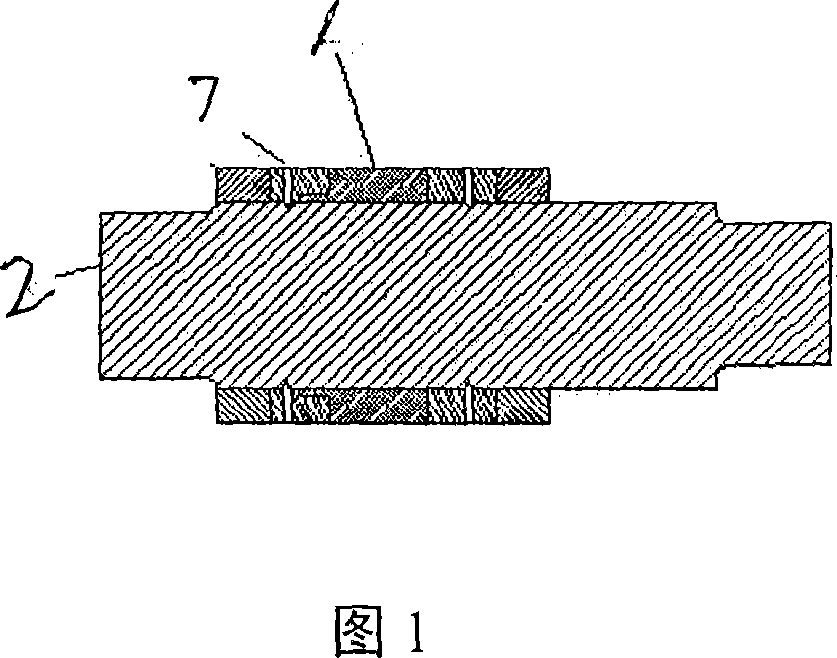
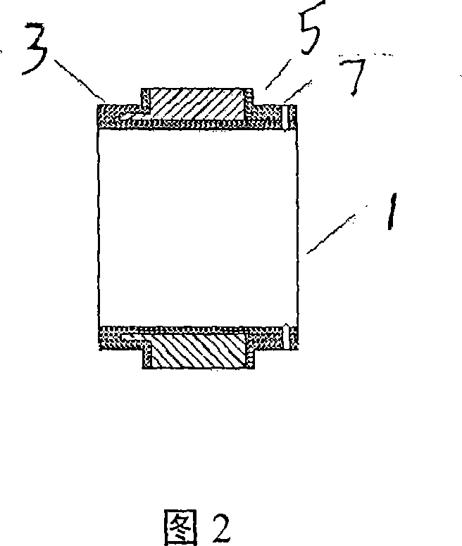
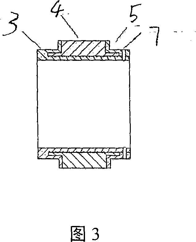
[0022] Example 1: Assume that a strip mill requires transmission torque M = 120KN.m, working face width h = 150mm, roll outer diameter D = 320mm, inner diameter d = 250mm, safety factor = 10, the calculation shows that for hard alloy without steps Composite roll rings or composite rolls require a shear strength of 81.5 MPa for the composite layer. Obviously, chemical bonding and compounding cannot achieve this strength. However, if the composite roll ring or composite roll with auxiliary steps is used, as long as a bonded step with length a=75mm and u=10mm is added to the cemented carbide roll ring, the shear strength of the cemented layer can reach 41MPa. Obviously, this is easy. achieved at an increased weight cost of only 6%.

example 2

[0023] Example 2: Assume that a pipe rolling mill requires transmission torque M = 120KN.m, working face width h = 120mm, roll outer diameter D = 320mm, inner diameter d = 260mm, safety factor = 10, the calculation shows that for no step cemented carbide composite For roll rings or composite rolls, the shear strength of the composite layer is required to be 102MPa. Obviously, chemical bonding methods cannot achieve this strength. However, if the composite roll ring or composite roll with auxiliary steps is used, as long as a bonded step with length a=100mm and u=10mm is added to the cemented carbide roll ring, the shear strength of the cemented layer can reach 34MPa. Obviously, this is easy achieved at an increased weight cost of only 12%.


PUM

PropertyMeasurementUnit
Thicknessaaaaaaaaaa
Shear strengthaaaaaaaaaa

Abstract

The invention is concerned with a compound roller for high performance cementation cemented carbide. It is made up of cemented carbide roller hoop and roller axis connecting with it. The said cemented carbide is made up of compound roller hoop seat, cemented carbide hoop and steel end face hoop. There is cemented carbide hoop cementing on the iron-based roller hoop seat and there is assistant cementation step hoop extending along the axis at least at one side of the cemented carbide hoop, and the iron-based roller hoop seat at one side of cemented carbide hoop connects with steel end face hoop. There are assistant cementation step hoops with equal or different extending of axis at both sides of the said cemented carbide hoop, and one end of it inserts and cements in the roller hoop seat and the other end of it inserts and cements in the end face hoop. The closed faces of the said end face hoop and cemented carbide roller hoop have bond grooves and cement with each other, and the end face hoop is connected and cemented with the roller hoop seat with bolt. The said cementation is inorganic or organic glue and forms at least one cementation layer with 1 to 3 mm thickness. It has easy production method, low cost and high compound intension and its torque transfer is much bigger than common cementation compound roller.

Description

technical field [0001] The invention relates to a cemented composite roll specially used for metal pressure processing equipment, especially a cemented carbide composite roll for bar and other small material rolling mills, which belongs to the main part of the metal rolling equipment. Background technique [0002] Cemented carbide rolls have excellent wear resistance, corrosion resistance and single-groove rolling life, and can significantly improve production efficiency and product quality, and have received more and more attention. For example, in the high-line finishing and pre-finishing stands, the integral cemented carbide roll composed of a cemented carbide roll ring and a roll shaft has been widely used. However, such solid carbide rolls are not suitable in terms of performance or economy for small bar mills such as larger bars that are required to withstand larger rolling loads and rolling torques. . [0003] In order to solve the problem of the application of ceme...

Claims


Application Information

Patent Timeline
IPC IPC(8): B21B27/02
Inventor 应金根傅肃嘉龙郑易
Owner ZHEJIANG METALLURGICAL RES INST
Why Eureka
Try Eureka