
Oil well drilling geological X-ray fluorescent debris logging method

An oil drilling and X-ray technology, applied in wellbore/well components, earthwork drilling, etc., can solve the problems of expensive instruments, long analysis cycle, strict sample and environmental requirements, etc., to reduce detection costs and shorten analysis. Cycle, the effect of cheap instruments

Inactive Publication Date: 2007-12-05
重庆奥能瑞科石油技术有限责任公司
View PDF2 Cites 28 Cited by
  • Summary
  • Abstract
  • Description
  • Claims
  • Application Information

AI Technical Summary

Problems solved by technology

Since the mid-1980s, the domestic petroleum industry has gradually introduced comprehensive mud logging technology. The surface data collection of most well sites uses instrumentation operations and artificial intelligence analysis, but cuttings logging still cannot be replaced by instruments.
This is not only because the geological origin of the rock is very complicated, but also because the vertical and horizontal regional characteristics of the rock itself are very different, so it is difficult to find a common and operable instrument identification method
In recent years, foreign countries have used X-ray diffraction, nuclear magnetic resonance and other methods to analyze cuttings while drilling. However, due to the strict requirements on samples and the environment, and the analysis period is too long (≥4min), it is impossible to follow the drilling speed in time and detect simultaneously. The current cuttings structure affects the drilling effect, the equipment is expensive, and the detection cost is high, so it cannot be widely promoted on the drilling site
[0003] With the emergence of new drilling technologies such as PDC bit drilling, gas drilling, and foam drilling, cuttings have become dusty, and artificial lithology identification methods have been phased out. Especially with the increasing drilling speed, horizontal wells, large The geosteering requirements of inclined wells make it more and more difficult to obtain cuttings samples at fixed points. There are currently no effective solutions to these problems at home and abroad
[0004] The disadvantages of the existing cuttings logging technology are: the equipment is expensive, the detection cost is high, and the analysis period is too long, and the formation structure cannot be obtained synchronously with the drilling speed in time

Method used

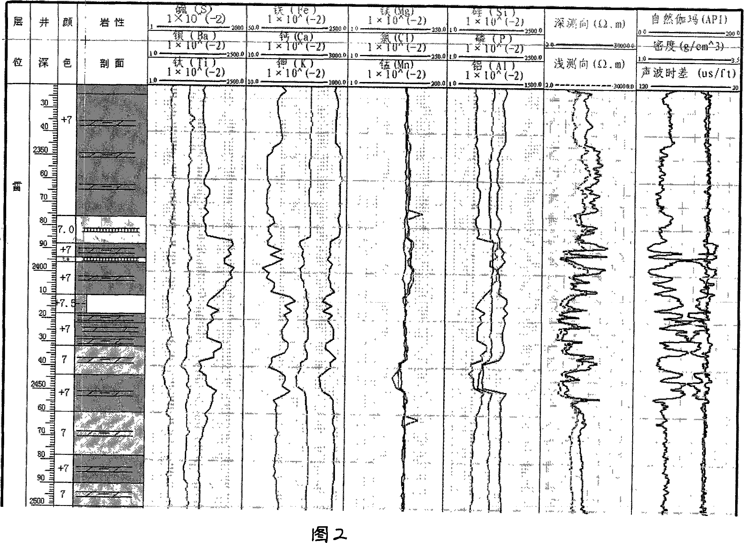
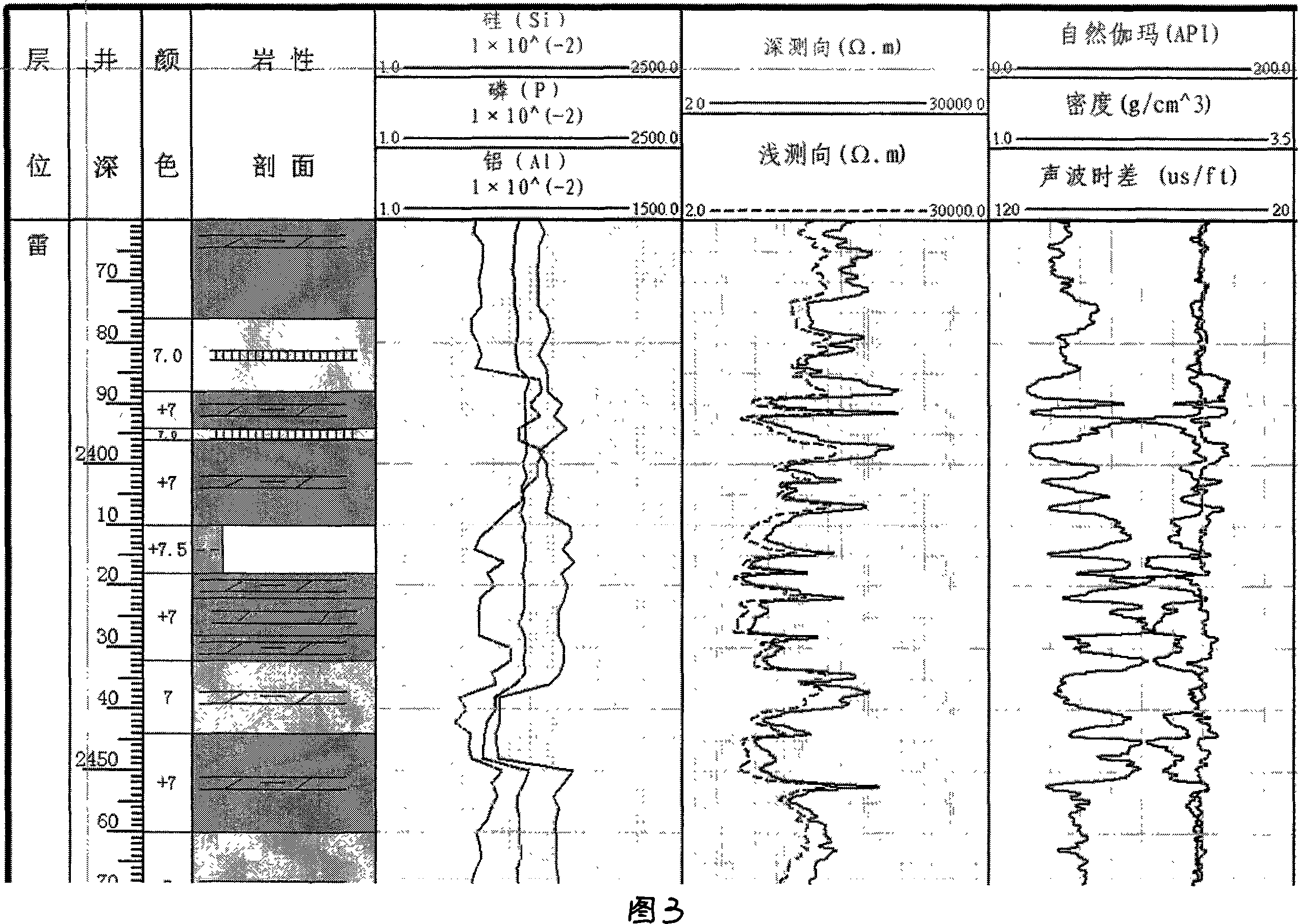

Image

  • Oil well drilling geological X-ray fluorescent debris logging method
  • Oil well drilling geological X-ray fluorescent debris logging method
  • Oil well drilling geological X-ray fluorescent debris logging method

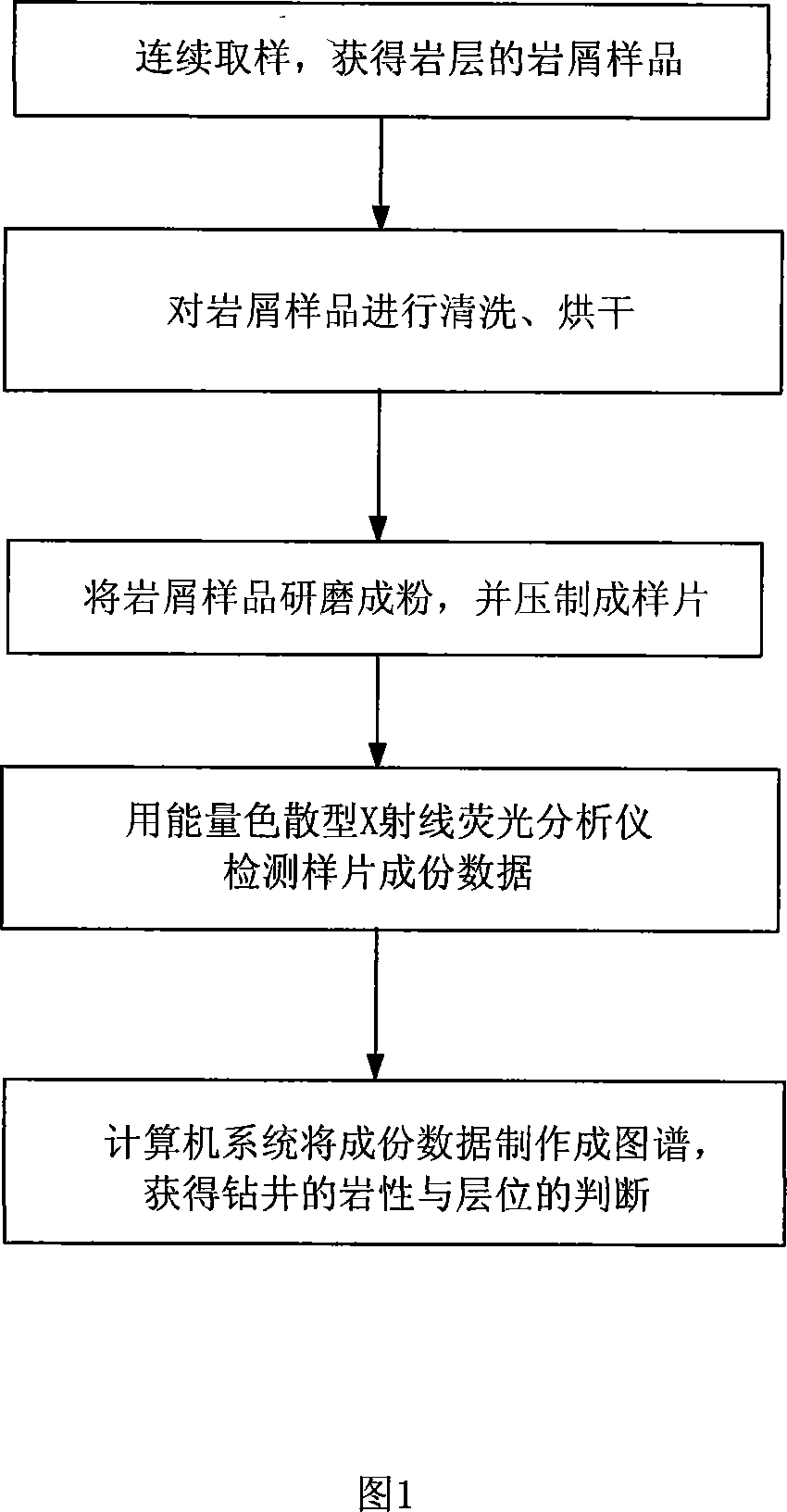
Examples


Embodiment Construction

[0027] The present invention will be described in further detail below in conjunction with the accompanying drawings and specific embodiments.

[0028] As shown in Figure 1:

[0029] A petroleum drilling geological X-ray fluorescence cuttings logging method, comprising the following steps:

[0030] Step 1: Continuously sample from shallow to deep according to the drilling depth to obtain cuttings samples of rock formations at each drilling depth; for every 1 meter of drilling, one cuttings sample is extracted.

[0031] Step 2, according to the drilling depth, clean the cuttings samples of each rock formation with clean water, and then dry the cuttings samples;

[0032] It only needs to be washed with clean water, and rapid detection can be carried out at room temperature, which reduces the detection cost.

[0033] Step 3: Grinding the rock chip samples of each rock formation into powder respectively, loading the sample powder into an extrusion die, and pressing the powder in...


PUM


Abstract

An X-ray fluorescence debris recording method of oil drilling geology is characterized in that: it contains the following steps: 1. sample from shallow to deep continuously on the drilling depth to get the debris samples of each drilling depth rock formation. 2. Clear the debris samples of each drilling depth rock formation on the drilling depth and dry these debris samples. 3. Grind the debris samples to powder and put them into the pressing die. Press the powder to print by using the tablemachine under the vacuum. 4. Test the component data of the print sequentially by using the energy dispersing-type X-ray fluorescence analyzer on the drilling depth. 5. The computer system makes the rock component data to the atlas on the drilling depth. Based on the analysis of the data and the atlas, the decision of the drilling lithologic characters and horizon is achieved. The distinct effects of this invention are: the cheap price, the low testing cost, the shorter analysis cyclic, the rock structure can be achieved simultaneously as the drilling speed.

Description

technical field [0001] The invention belongs to oil and natural gas drilling technology, in particular to an oil drilling geological X-ray fluorescent cuttings logging method in geological logging engineering on the oil drilling site. Background technique [0002] The traditional methods of petroleum geological cuttings logging technology are all manual operations, that is, after obtaining cuttings samples, rely on the engineer's naked eye observation experience or simple chemical analysis to determine the rock properties, and then determine the cuttings layer (geological age). Follow the drilling speed of the rock formation to carry out sampling detection, so as to obtain the current structural level of the rock formation, so as to directly and timely grasp and reasonably control the drilling depth. The analyzer (application number: 200720124483.1) provides equipment for collecting rock formation samples online. Since the mid-1980s, the domestic petroleum industry has grad...

Claims


Application Information

Patent Timeline
IPC IPC(8): E21B49/00
Inventor 朱根庆刘德伦李春山罗利朱直箐刘华
Owner 重庆奥能瑞科石油技术有限责任公司
Learn More