
Micro-wave vacuum equipment

A technology of microwave vacuum drying and equipment, which is applied in the direction of drying solid materials, drying chamber/container, lighting and heating equipment, etc. It can solve the problems of great influence on the quality of dried food, high energy consumption, long time, etc., and achieve drying or concentration The effect of fast speed and low temperature

Inactive Publication Date: 2007-12-05
JIANGNAN UNIV
View PDF0 Cites 65 Cited by
  • Summary
  • Abstract
  • Description
  • Claims
  • Application Information

AI Technical Summary

Problems solved by technology

Hot air dryers generally have a higher drying temperature, and oxygen exists during the drying process, which has a great impact on the quality of dried food, and the loss and degradation of vitamins, natural pigments and other heat-sensitive components in food are more; although vacuum drying has a lower drying temperature, it can be controlled. to below 60°C, but since the heat supply of materials is mainly through heat conduction, there is almost no convective heat transfer in the drying room, the drying speed is slow, the time is long, and the retention of heat-sensitive or biologically active components is also limited; the freeze-drying process is divided into two steps: product Freezing and sublimation drying. Freezing is generally below -20°C, so that the water in the product becomes small ice crystals. The pressure in the sublimation stage must be below the pressure of the triple point (627pa). Freeze drying can retain the original shape of the dried product , to minimize the loss of color, fragrance and biologically active substances, but the drying time is long (generally takes 15-22 hours), and the energy consumption is large
The concentrated materials in the laboratory mainly use rotary evaporators, but the time is long

Method used


Image

  • Micro-wave vacuum equipment
  • Micro-wave vacuum equipment

Examples


Embodiment Construction

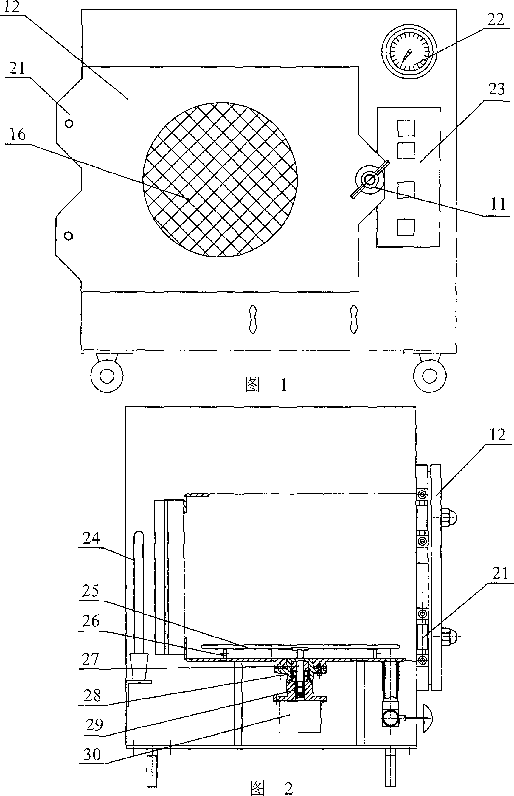
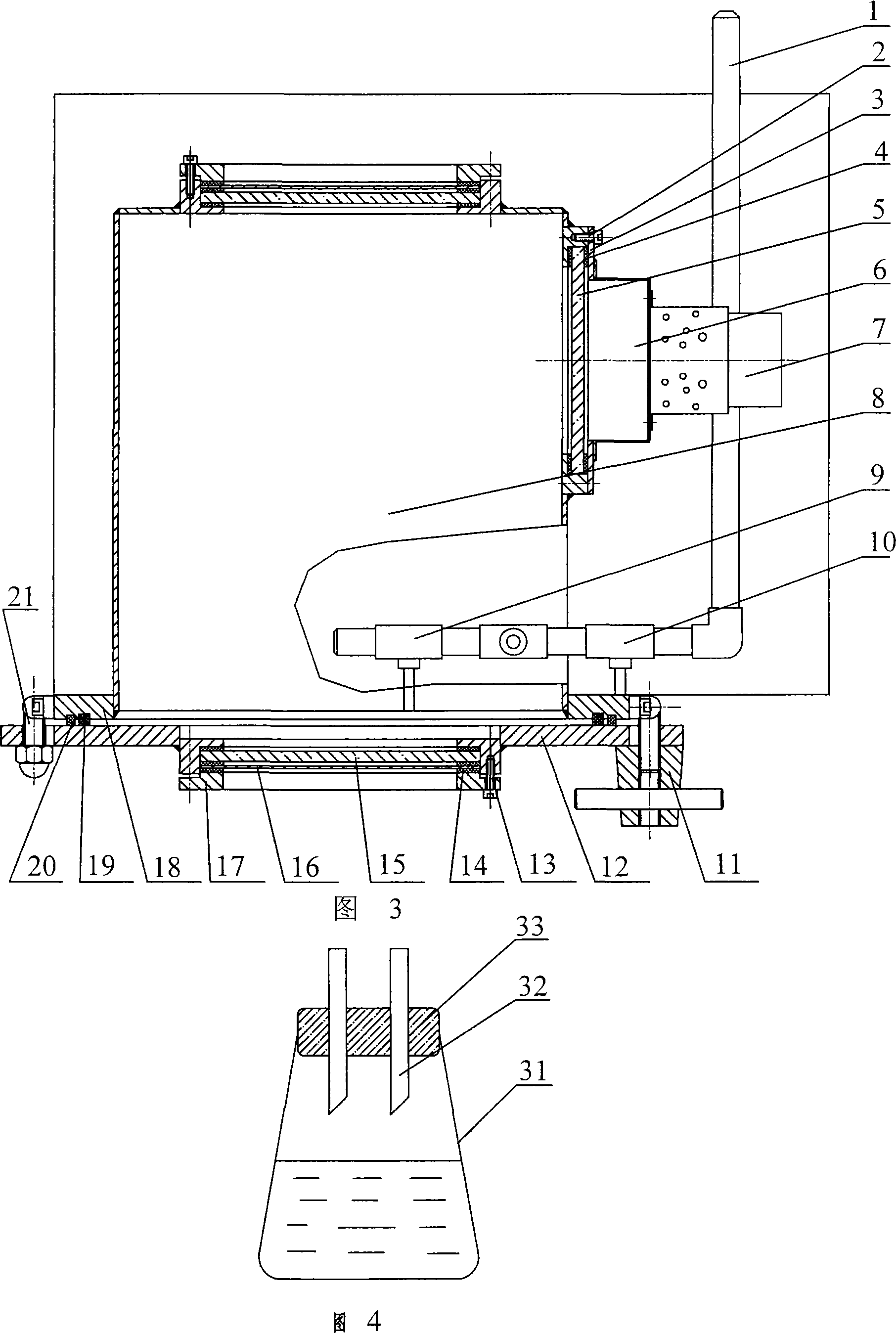
[0012] In the figure, 1 is the vacuum connection, 2 is the hexagonal bolt, 3 is the pressure plate, 4 is the gasket, 5 is the polypropylene plate, 6 is the waveguide, 7 is the magnetron, 8 is the drying chamber (resonant cavity), 9 is Vacuum breaking valve, 10 is the vacuum pipeline valve, 11 is the lock nut, 12 is the door, 13 is the hex nut, 14 is the gasket, 15 is the mirror glass, 16 is the metal mesh, 17 is the gland, 18 is the door method Lan, 19 is a rectangular silicone rubber sealing ring, 20 is a metal sealing ring, 21 is a door hinge, 22 is a vacuum gauge, 23 is a controller, 24 is a lamp, 25 is a turntable, 26 is a roller, 27 is a rotating shaft, and 28 is a Skeleton oil seal, 29 is a shaft coupling, and 30 is a motor.

[0013] As shown in the figure: a vacuum gauge 22, an operation controller 23 and a lamp 24 are arranged on the outer wall of the drying chamber 8, and an opening and closing door 12 for taking and putting materials is arranged on the wall of the dr...


PUM


Abstract

This invention relates to a sort of integral dry and dewatering set of the microwave and vacuum system, it consists of a hothouse of hermetic estate which is used to pose the materiel, the on-off door body which is propitious to gain and put materiel is fitted on the wall of the hothouse, the microwave produced by the microwave generator can cross the wall of the hothouse and it use the microwave to heat the materiel of the hothouse, there has the vacuum connector tub which is extended to the hothouse on the wall of the hothouse, the vacuum connector tub connects with the vacuum-pumping set. Because thin invention makes the microwave heating system connects with the vacuum system in the organic way, the speed of its dryness and condensation is fast, the temperature is low (25 to 45 deg. C), It very fit to the use of the lab, and fit to desiccate and condense the multifarious hydrous, and specially fit to food materiel of the heat sensitivity, and so on, and it is widely used to desiccate and condense the multifarious hydrous in the way of small-scale in the lab, such as the food, the medication, the chemical production.

Description

technical field [0001] The invention relates to a small microwave drying and dehydrating equipment, in particular to a drying and dehydrating equipment integrating microwave and vacuum systems. Background technique [0002] At present, the laboratory drying of water-containing materials mainly uses electric blast dryers, electric or steam heating vacuum dryers and freeze dryers. The hot air dryer generally has a higher drying temperature, and oxygen exists during the drying process, which has a great impact on the quality of dried food, and the loss of vitamins, natural pigments and other heat-sensitive components in the food is more degraded; although the drying temperature of vacuum drying is lower, it can be controlled. to below 60°C, but since the heat supply of materials is mainly through heat conduction, there is almost no convective heat transfer in the drying chamber, the drying speed is slow, the time is long, and the retention of heat-sensitive or biologically acti...

Claims


Application Information

Patent Timeline
Patent Type & Authority Applications(China)
IPC IPC(8): F26B9/10F26B3/347F26B25/06
Inventor 崔政伟
Owner JIANGNAN UNIV
Learn More