

Method for removing acid gases in cracked gas
A technology of acid gas and cracked gas
- Summary
- Abstract
- Description
- Claims
- Application Information
AI Technical Summary
Problems solved by technology
Method used
Image

Examples
Embodiment Construction
[0053] In order to better understand the present invention, the following examples are provided, but the present invention is not limited to the examples.
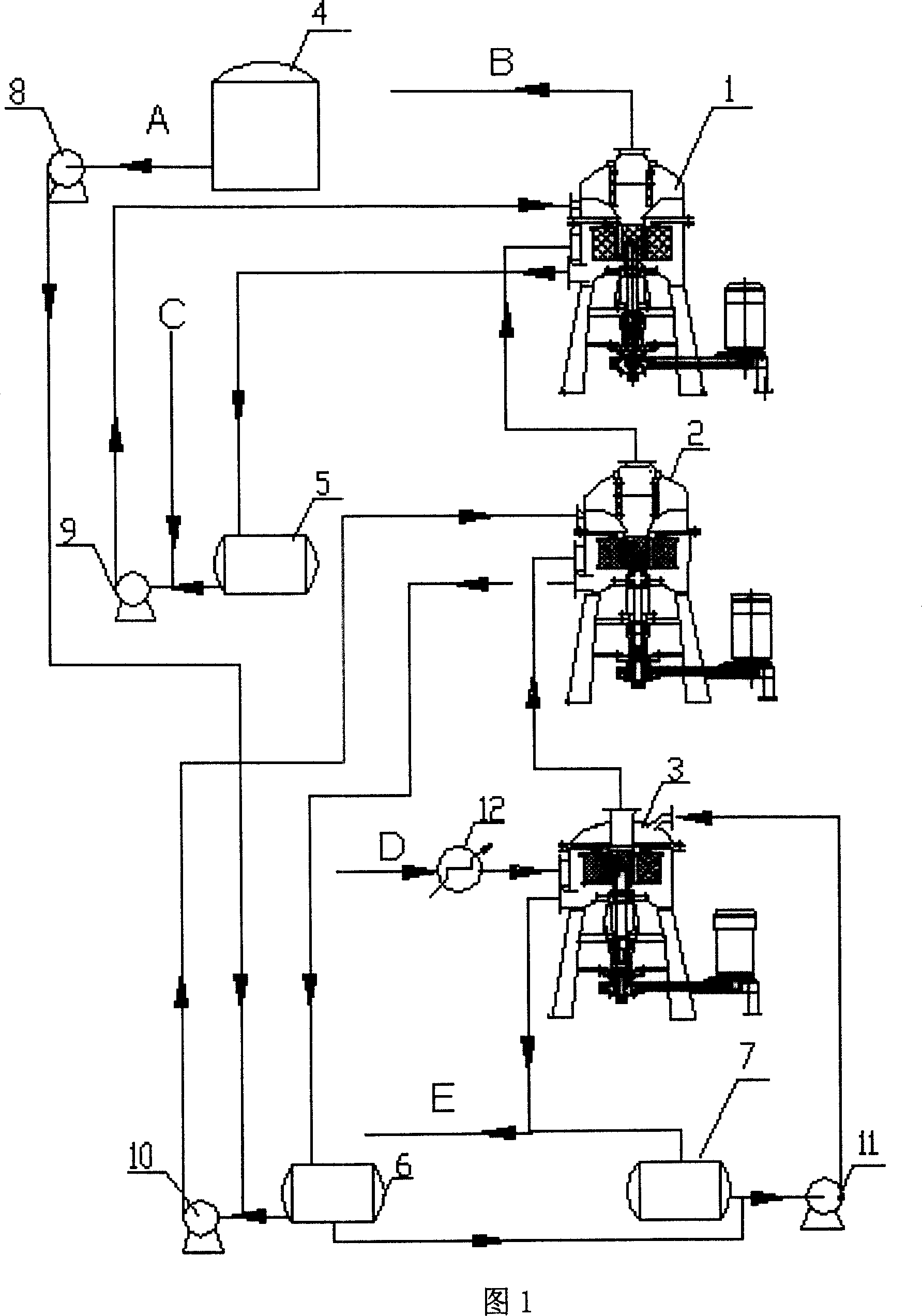
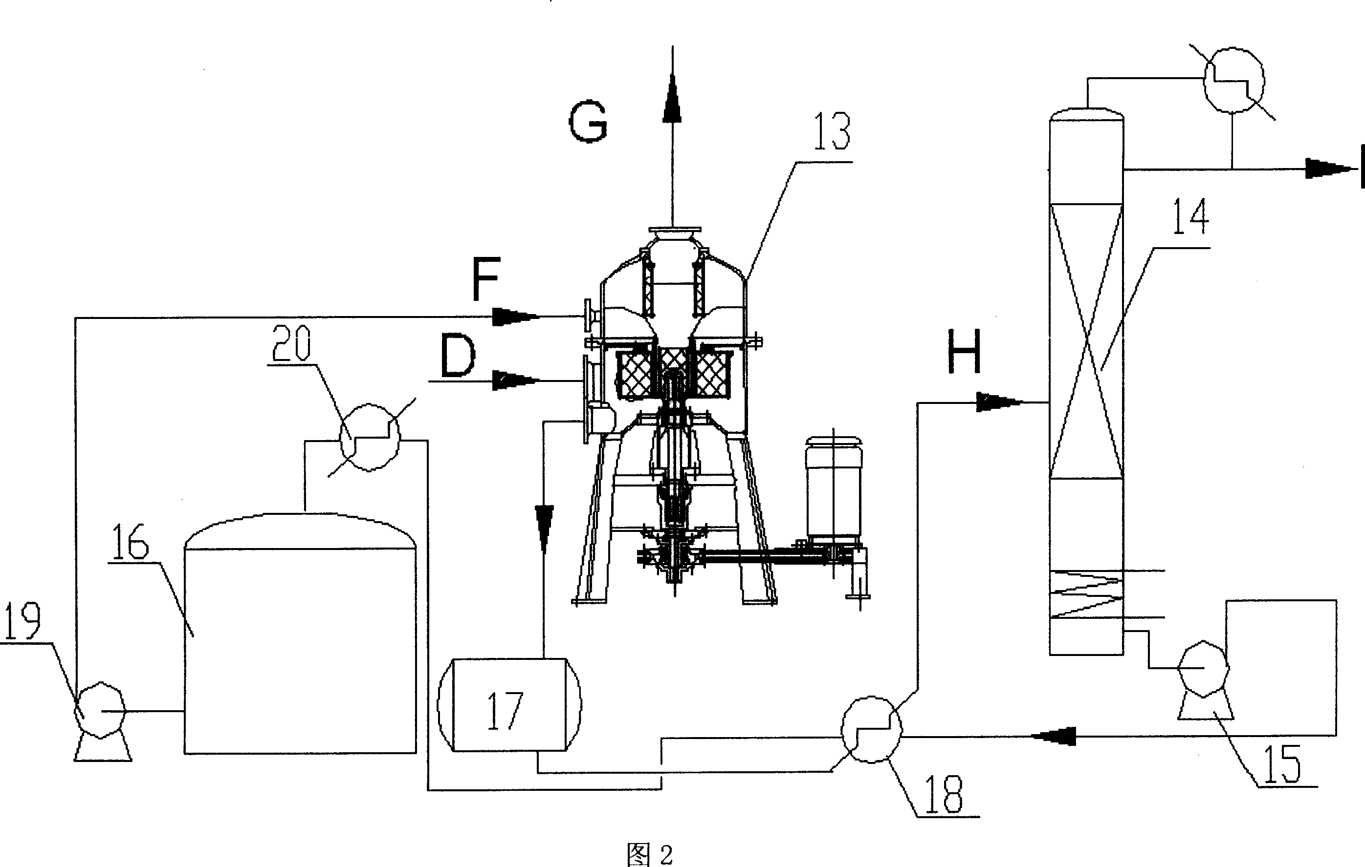
[0054] Below in conjunction with the alkaline cleaning section of the ethylene process with an annual output of 800,000 tons, the process of using the absorption tower and the high-gravity rotating bed for alkaline cleaning is compared to illustrate the effect of the present invention.
[0055] Annual output of 800,000 tons of ethylene process, flow rate of cracked gas: 296.18 tons / hour, pressure 1698KPa, temperature 46°C, composition of cracked gas is shown in Table 1. The gas-liquid phase load of each section is shown in Table 2. After treatment, the total content of carbon dioxide and hydrogen sulfide in the cracked gas is less than 1ppm.
[0056] Table 1 cracked gas composition (unit: mol%)
[0057] h 2 o
H 2
CO
CO 2
h 2 S
CH 4
C 2
C 3
C 4
C 5 above ...
PUM
 Abstract
Description
Claims
Application Information