Waste gases filtering equipment

A technology of exhaust gas filtration and filtration devices, which is applied in the direction of exhaust devices, combination devices, noise reduction devices, etc., and can solve problems such as high power consumption, high operating costs, and narrow applicability

Inactive Publication Date: 2008-01-02
陈友年
View PDF0 Cites 9 Cited by
  • Summary
  • Abstract
  • Description
  • Claims
  • Application Information

AI Technical Summary

Problems solved by technology

But all there is the problem (such as sulfur dioxide and carbon dioxide etc.) that is harmful to human body in the waste gas produced by petrochemical products or coal in the waste gas that is filtered according to above-mentioned these waste gas filtration methods more reliably or filter, thereby The air filtered by it is directly discharged to the outside, which will still pollute the atmosphere to a certain extent, such as acid rain that destroys forests, building surfaces, human health, etc.
In addition, the above exhaust gas filtering devices generally have complex structures, large volumes, high power consumption and high operating costs, and narrow applicability, so they are not suitable for filtering indoor air in ordinary households.

Method used


Image

  • Waste gases filtering equipment
  • Waste gases filtering equipment
  • Waste gases filtering equipment

Examples


Embodiment 1

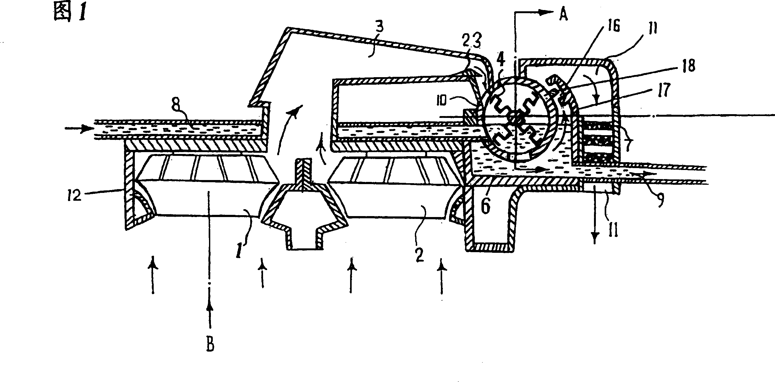
[0011] Fig. 1 shows a kind of pollution-free range hood (or called range hood), wherein, a double filtering device is installed at the rear of the exhaust pipe of the range hood.

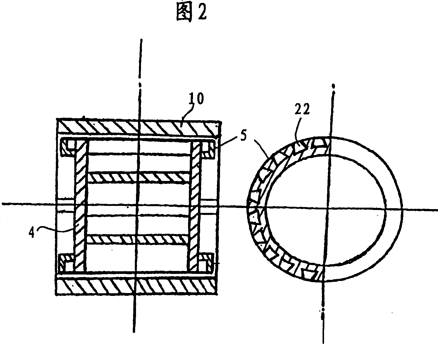
[0012] As shown in Figure 1, when working, using the strong high-speed wind generated by the fan 1 and the fan 2 installed in the range hood cover 12, hot air such as steam and oil smoke will be sucked together to generate a strong air flow, and then flow into the air. In a gradually narrowing exhaust pipe 3. The purpose of designing this pipeline to gradually narrow is to make the gas in the flow generate strong compression and high-pressure injection blowing power, because when the compressed gas flows into the ducted casing 10, the compressed gas will expand rapidly and the pressure will increase. Multiplied, so that the airflow becomes a high-pressure and strong airflow, and then the gas-water mixing wheel 4 is strongly promoted to rotate. Because a part of the rotor body of the air-water mixin...

Embodiment 2

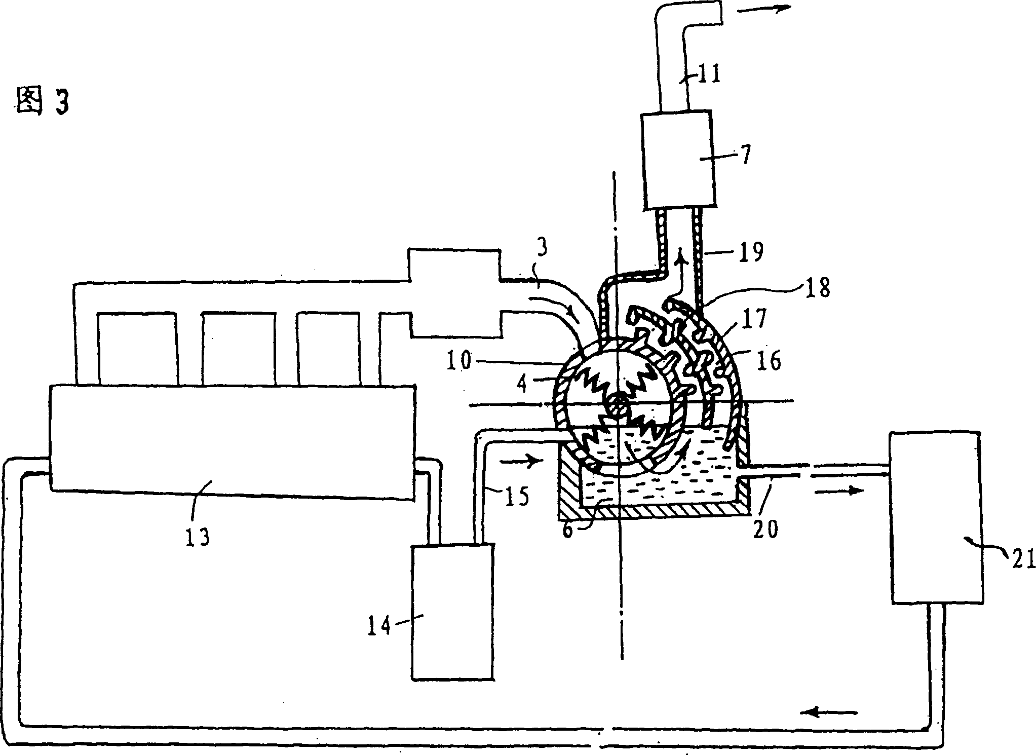
[0019] Fig. 3 shows Embodiment 2 of the present invention, which relates to an exhaust system suitable for use by vehicles and ships, wherein components with the same structure as Embodiment 1 are represented by the same symbols. As shown in Figure 3, the waste gas blowdown system is connected to the internal combustion engine case 13 of the vehicle or ship. When the internal combustion engine is working, the exhaust gas generated flows into the exhaust pipe 3. Due to the narrowing of the pipeline, the exhaust gas is compressed and then discharged in the engine. The rapid expansion inside the shell 10 pushes the air-water mixing wheel 4 to rotate, creating a water tornado and mixing the exhaust gas and clean water, so that various toxic substances in the exhaust gas dissolve and adhere to the water. Simultaneously, the cooling water pumped out from the internal combustion engine is pumped into the water tank 6 through the water pipe 15 after passing through the cooler 14 . Bec...

Embodiment 3

[0026]FIG. 4 shows Embodiment 3 of the present invention. This embodiment applies the working principle of the range hood of the present invention to exhaust gas systems of various factories, such as cement plants, power plants, smelters or various chemical plants and incinerators. Components with the same structure as in Embodiment 1 are denoted by the same reference numerals. After the waste gas is discharged from the exhaust chimney 25 and enters the narrowed exhaust pipe 3, it will be sucked in by the rotating gas-water mixing wheel 4, so that the waste gas is mixed with water. A variety of toxic substances contained in the exhaust gas dissolve and adhere to the water, while relatively coarse dust or incompletely burned coal dust will flow into the water tank 6 under the centrifugal force of the gas-water mixing wheel 4, and then settle in the sedimentation tank 24 Therefore, it is only necessary to take out the whole box of the settled dust regularly and replace it with ...


PUM


Abstract

The invention relates to a filtering device for waste gas, comprising exhaust pipe, of which one end is connected with generating device of waste gas; double filtering device constituted by a filtering device of water tank and a filter, which is connected with the other end of exhaust pipe; and fish-gill anti-overflow device. The filter is located in the middle of gas outlet pipe. The gas outlet pipe is used to connect the filtering device of water tank and the filter. The invention is provided with simple structure, lower power exhaustion, lower cost and smaller cubage. It can be used in waste gas discharging systems of vehicle and ship, lampblack presser, refreshing machine for indoor air and various factories.

Description

technical field [0001] The invention relates to an exhaust gas filtering device. Background technique [0002] Various existing exhaust gas devices are generally used to filter the exhaust gas produced by internal combustion engines on ships and vehicles or high-heat boilers used in power plants and factories. Dry filters are usually used, and the commonly used filtering method There are winding pipeline methods, multi-layer paper or wire mesh methods, mineral mesh layer methods, etc., or large devices such as electrostatic precipitators are used. But all there is the problem (such as sulfur dioxide and carbon dioxide etc.) that is harmful to human body in the waste gas produced by petrochemical products or coal in the waste gas that is filtered according to above-mentioned these waste gas filtration methods more reliably or filter, thereby If the filtered gas is directly discharged to the outside, it will still pollute the atmosphere to a certain extent, such as producing ...

Claims


Application Information

Patent Timeline
Patent Type & Authority Applications(China)
IPC IPC(8): B01D50/00F01N3/04F01N3/021
Inventor 陈友年
Owner 陈友年
Why Eureka
Try Eureka