Field-emissive cathode X ray tube
A field emission and X-ray tube technology, applied in X-ray tubes, X-ray tube electrodes, X-ray tube components, etc., can solve the problems of low detection and imaging rate, low detection and imaging efficiency, and difficult application solutions , to achieve the effects of improving detection resolution and response speed, improving maneuverability, reducing cost and process difficulty
- Summary
- Abstract
- Description
- Claims
- Application Information
AI Technical Summary
Problems solved by technology
Method used
Image
Examples
Embodiment 1
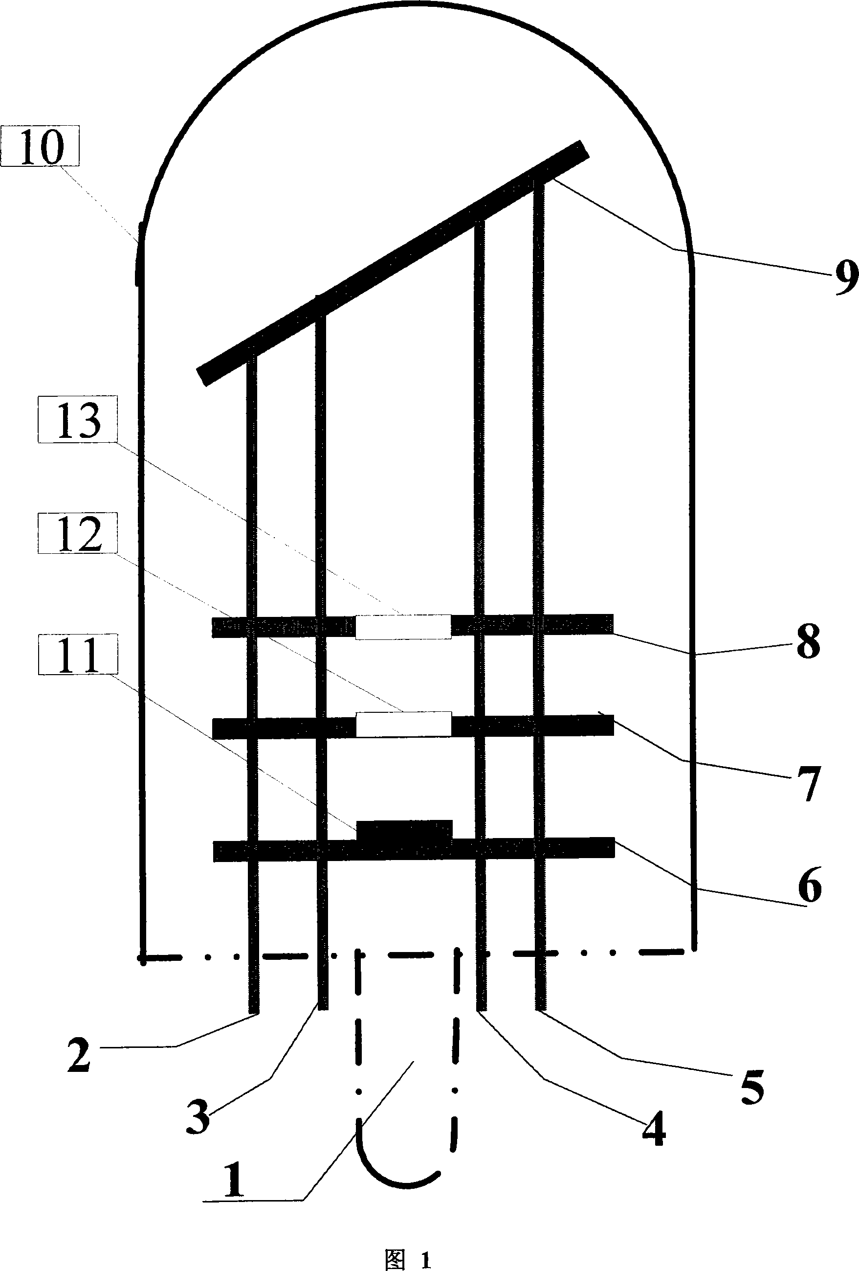
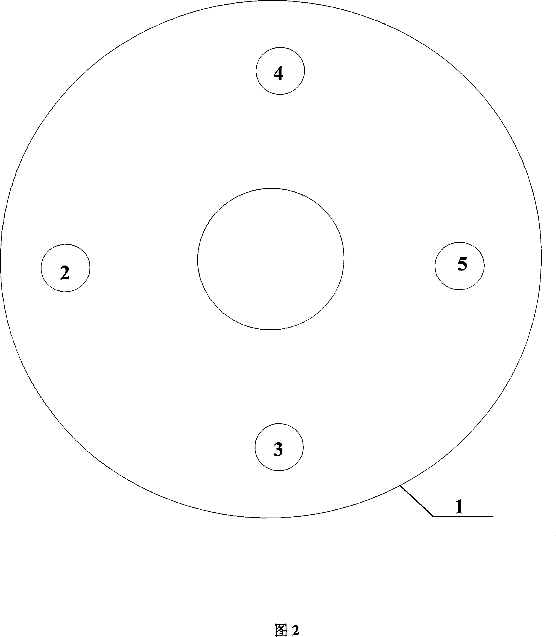
[0014] Use spot welding technology to connect the lead wire and the nickel wire of the ceramic rod, and spot weld it on the anode / target; use spot welding technology to connect the lead wire and the nickel wire of the ceramic rod respectively, and the ceramic rod passes through the circular oxygen-free copper in turn Field emission cathode sheet, circular oxygen-free copper modulation grid sheet and circular oxygen-free copper focusing electrode sheet have via holes; at the via holes, the nickel wire in the ceramic rod is respectively connected to the circular oxygen-free copper field by spot welding. The emission cathode sheet, the circular oxygen-free copper modulation grid sheet, and the circular oxygen-free copper focusing electrode sheet are connected; the three electrode sheets are placed opposite and parallel, and the distance between the cathode and the grid is 250 microns; the height of the elliptical oxygen-free copper The voltage anode target is spot-welded on the ot...
Embodiment 2
[0016] Use spot welding technology to connect the lead wire and the nickel wire of the ceramic rod, and spot weld it on the anode / target; use spot welding technology to connect the lead wire and the nickel wire of the ceramic rod respectively, and the ceramic rod passes through the circular oxygen-free copper in turn Field emission cathode sheet, circular oxygen-free copper modulation grid sheet and circular oxygen-free copper focusing electrode sheet have via holes; at the via holes, the nickel wire in the ceramic rod is respectively connected to the circular oxygen-free copper field by spot welding. The emission cathode sheet, the circular oxygen-free copper modulation grid sheet, and the circular oxygen-free copper focusing electrode sheet are connected; the three electrode sheets are placed opposite and parallel, and the distance between the cathode and the grid is 125 microns; the height of the elliptical oxygen-free copper The voltage anode target is spot-welded on the ot...
Embodiment 3
[0018] Use spot welding technology to connect the lead wire and the nickel wire of the ceramic rod, and spot weld it on the anode / target; use spot welding technology to connect the lead wire and the nickel wire of the ceramic rod respectively, and the ceramic rod passes through the circular oxygen-free copper in turn Field emission cathode sheet, circular oxygen-free copper modulation grid sheet and circular oxygen-free copper focusing electrode sheet have via holes; at the via holes, the nickel wire in the ceramic rod is respectively connected to the circular oxygen-free copper field by spot welding. The emission cathode sheet, the circular oxygen-free copper modulation grid sheet, and the circular oxygen-free copper focusing electrode sheet are connected; the three electrode sheets are placed opposite and parallel, and the distance between the cathode and the grid is 200 microns; the height of the elliptical oxygen-free copper The voltage anode target is spot-welded on the ot...
PUM
 Abstract
Description
Claims
Application Information
 - R&D
- Intellectual Property
- Life Sciences
- Materials
- Tech Scout
- Unparalleled Data Quality
- Higher Quality Content
- 60% Fewer Hallucinations
Browse by: Latest US Patents, China's latest patents, Technical Efficacy Thesaurus, Application Domain, Technology Topic, Popular Technical Reports.
© 2025 PatSnap. All rights reserved.Legal|Privacy policy|Modern Slavery Act Transparency Statement|Sitemap|About US| Contact US: help@patsnap.com


