
Pure phase type broad frequency band microwave radiation source direction finding system and method

A microwave radiation and direction-finding device technology, which is applied in measuring devices, direction-determining directional devices, radio wave measurement systems, etc., can solve the problem that channel phase balance and amplitude balance are difficult to be satisfied at the same time, and it is difficult to ensure accurate direction finding, etc. problem, to achieve the effect of simple structure and easy engineering realization

Inactive Publication Date: 2008-01-16
HARBIN ENG UNIV
View PDF0 Cites 33 Cited by
  • Summary
  • Abstract
  • Description
  • Claims
  • Application Information

AI Technical Summary

Problems solved by technology

Most of the existing wide-band passive radar detection devices adopt a direction finding system combining amplitude and phase ratios, using ratio-amplitude direction-finding to eliminate the multi-value ambiguity of high-frequency direction-finding of phase interferometers, and using phase-comparison direction-finding to improve direction-finding accuracy , the whole system is divided into phase comparison branch and amplitude ratio branch. It is difficult to satisfy the phase balance and amplitude balance of the channel at the same time, so it is difficult to ensure accurate direction finding in a wide frequency band with this method

Method used


Image

  • Pure phase type broad frequency band microwave radiation source direction finding system and method
  • Pure phase type broad frequency band microwave radiation source direction finding system and method
  • Pure phase type broad frequency band microwave radiation source direction finding system and method

Examples


Embodiment Construction

[0015] The present invention is described in more detail below in conjunction with accompanying drawing example:

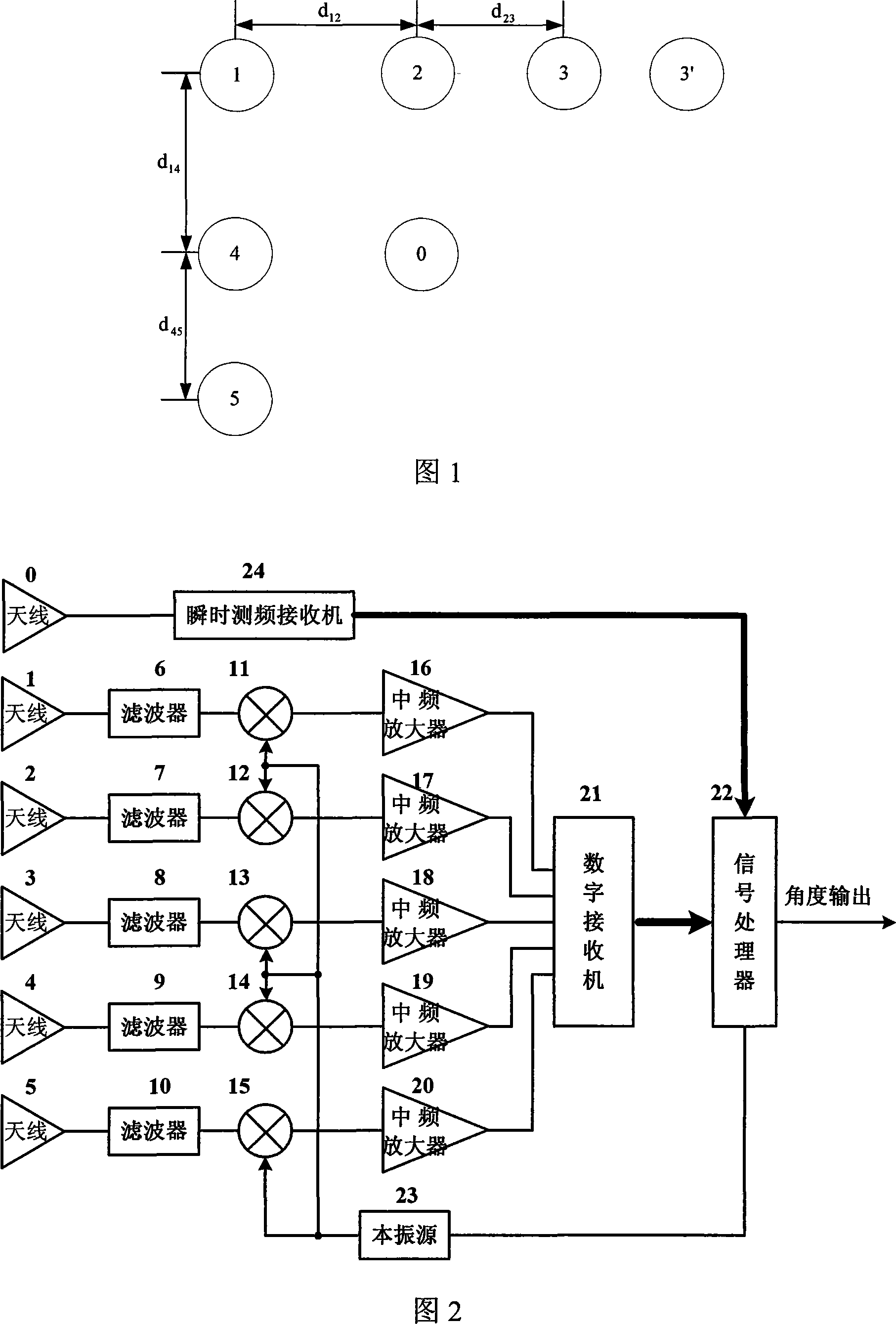
[0016] Combined with Figure 1, the five antennas connected to the digital receiver are arranged in an L shape, and antenna 0 is used to connect to the instantaneous frequency measurement receiver to measure the frequency of the microwave radiation source, and has d 12 > d 23 , d 14 > d 45 , and d 12 -d 23 23 , d 14 -d 45 45 . Antennas 1, 2, and 3 are used for direction finding on the azimuth plane, and antennas 1, 4, and 5 are used for direction finding on the elevation plane. According to the frequency band coverage and angle measurement range and signal-to-noise ratio of the angle measurement system, the intervals between antennas 1, 2, 2, 3, 1, 4, 4, and 5 must satisfy a certain relationship. Take the antenna placement on the azimuth plane as an example, assuming that the wavelength corresponding to the highest frequency covered by the system is λ min ...


PUM


Abstract

The invention provides a pure phase type broadband microwave radiation source direction-finding device and a direction-finding method; the pure-phase type broadband microwave radiation source direction-finding device comprises a digital receiver, an instantaneous frequency measurement receiver and a signal processor; wherein each passage of the digital receiver consists of an antenna, a filter, a frequency mixer and an intermediate frequency amplifier; the intermediate frequency amplifier is connected with the digital receiver; microwave signals which are generated by local oscillator source connected with the signal processor and has fixing frequency difference with incident signal frequency and output signals of the filter are input into the frequency mixer, and intermediate frequency signals with fixing frequency are obtained. Based on phase position interferometer direction finding, the microwave radiation source direction-finding method adopting pure phase utilizes the phase position difference between long base line and short base line, establishes virtual short base line, implements ambiguity resolution by combining physical reliable long base line and short base line, resolves the contradiction between the covering bandwidth of the phase position interferometer and the angle-finding range of the phase position interferometer, and can realize rapid accurate direction finding of space microwave radiation source in broadband only by the utilization of phase position information.

Description

technical field [0001] The invention relates to a microwave radiation source detection device and detection method. Background technique [0002] The operating frequency range of modern radar systems is very wide, covering the meter wave band to the millimeter wave band. Therefore, the passive radar detection device must also have a wide frequency coverage, and at the same time, it must have sufficient angle measurement accuracy and fast signal processing speed. Most of the existing wide-band passive radar detection devices adopt a direction finding system combining amplitude and phase ratios, using ratio-amplitude direction-finding to eliminate the multi-value ambiguity of high-frequency direction-finding of phase interferometers, and using phase-comparison direction-finding to improve direction-finding accuracy , the whole system is divided into phase comparison branch and amplitude ratio branch. It is difficult to satisfy the phase balance and amplitude balance of the cha...

Claims


Application Information

Patent Timeline
IPC IPC(8): G01S3/48
Inventor 司伟建曲志昱司锡才谢纪岭初萍
Owner HARBIN ENG UNIV
Learn More