Method and apparatus for producing catalyst layer for fuel cell
A catalyst layer, fuel cell technology, applied in fuel cells, nanotechnology for materials and surface science, battery electrodes, etc., can solve problems such as insufficient improvement, to simplify the manufacturing process, improve fuel cell performance, and reduce manufacturing. cost effect
- Summary
- Abstract
- Description
- Claims
- Application Information
AI Technical Summary
Problems solved by technology
Method used
Image

Examples
example 1
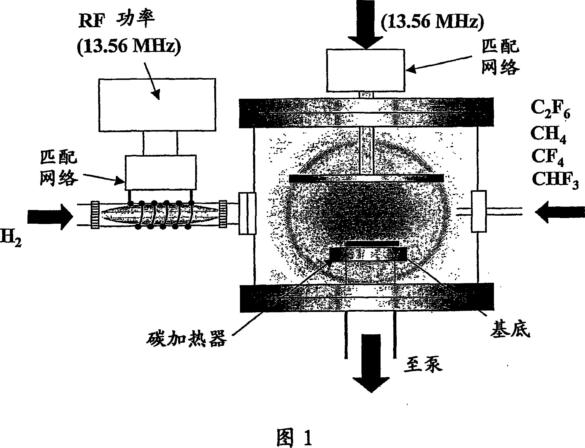
[0049] The process of manufacturing a catalyst layer thin film using the one-step catalyst layer manufacturing device shown in FIG. 4 is described. In this example, CNW is used as the diffusion layer carrier. In the same cavity, a carrier (CNW) is manufactured, and a laser or plasma is used to load and disperse the catalyst components and the electrolyte (proton conductive material) on the carrier to manufacture a catalyst layer. For the loading / dispersion of the catalyst component and the electrolyte (proton conductive material), for example, a laser ablation method, a plasma method, or an arc discharge method is used. In this example, the catalyst components and the electrolyte are dispersed sequentially or simultaneously.
[0050] The source gas is composed of hydrocarbons and halogen-containing hydrocarbons. The proton conductor is composed of substances with sulfonic acid groups, phosphoric acid groups, hydroxyl groups, imidazole groups, solid acid salts, tropolone, ionic liq...
example 2
[0068] Next, the process of manufacturing the catalyst layer thin film using another one-step manufacturing device of the catalyst layer shown in FIG. 5 will be described. In this example, in addition to the high frequency that generates plasma, a lower high frequency is applied to the same electrode. In this way, by placing a catalyst metal such as platinum on the electrode surface in advance, the metal nanoparticles jump into the plasma by plasma sputtering and are supported on the CNW surface. It is also possible to supply a gas or solution containing a catalyst metal into the plasma to support the catalyst metal on the CNW. Among them, the method of supply may include nozzles and so on.
example 1 and 2
[0069] Examples 1 and 2 produce the following effects:
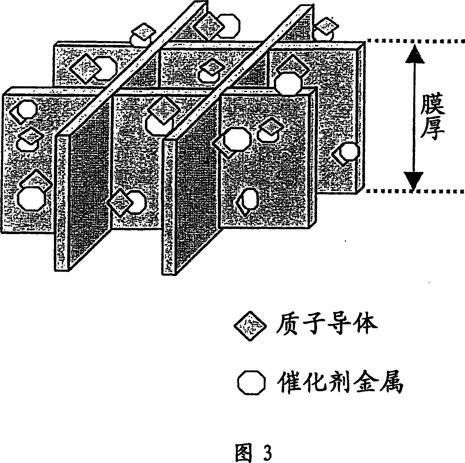
[0070] (1) The use of CNW eliminates the need to form a film in the subsequent processing steps. One-step manufacturing can reduce costs and reduce equipment size. (2) The catalyst components and electrolytes can be highly dispersed. The amount of electrolyte to be mixed can also be easily controlled, so that the problem that the electrolyte covering the platinum group catalyst reduces the activity of the platinum group catalyst can be prevented. The amount of platinum group catalyst used can be reduced, thereby reducing costs.
[0071] FIG. 6 shows a flowchart of an example of the sequence of forming a film according to the present invention. Figure 6 (a) shows the following situation, in which in the same cavity: (1) vapor-grown carbon nanowall (CNW) as a carrier for the catalyst layer; then, (2) the catalyst components are supported and dispersed On the carrier for the catalyst layer, and at the same time (3) the electrolyt...
PUM
| Property | Measurement | Unit |
|---|---|---|
| angle | aaaaa | aaaaa |
Abstract
Description
Claims
Application Information