Making method for blue top organic LED based on electronic acceptance material

A technology of electron acceptor materials and light-emitting diodes, which is applied in the direction of electrical solid-state devices, semiconductor/solid-state device manufacturing, circuits, etc., can solve the problems of reducing the luminous efficiency of devices, achieve convenient transmission and recombination, improve luminous brightness and efficiency, and high Effects of Luminous Brightness and Luminous Efficiency

Inactive Publication Date: 2008-02-13
INST OF CHEM CHINESE ACAD OF SCI
View PDF0 Cites 1 Cited by
  • Summary
  • Abstract
  • Description
  • Claims
  • Application Information

AI Technical Summary

Problems solved by technology

However, the introduction of strong electron-withdrawing groups will make it easy for material molecules to form charge-transfer exciplexes with hole-transport materials (usually electron donors), resulting in the emission peak of the device appearing in the long-wavelength direction and reducing the Device Luminous Efficiency

Method used


Image

  • Making method for blue top organic LED based on electronic acceptance material
  • Making method for blue top organic LED based on electronic acceptance material
  • Making method for blue top organic LED based on electronic acceptance material

Examples


preparation example Construction

[0032] The preparation process of the present invention is:

[0033] A) Vacuum-deposit one or two layers of hole transport material on the cleaned ITO (tin indium oxide, as anode) glass substrate.

[0034] B) Vacuum evaporation of an exciplex elimination material on the hole transport material layer.

[0035] C) Vacuum-evaporating a blue light-emitting material with strong electron-withdrawing ability on the exciplex elimination material.

[0036] D) Vacuum evaporation of a cathode layer on the blue luminescent material.

[0037] The present invention has the following characteristics:

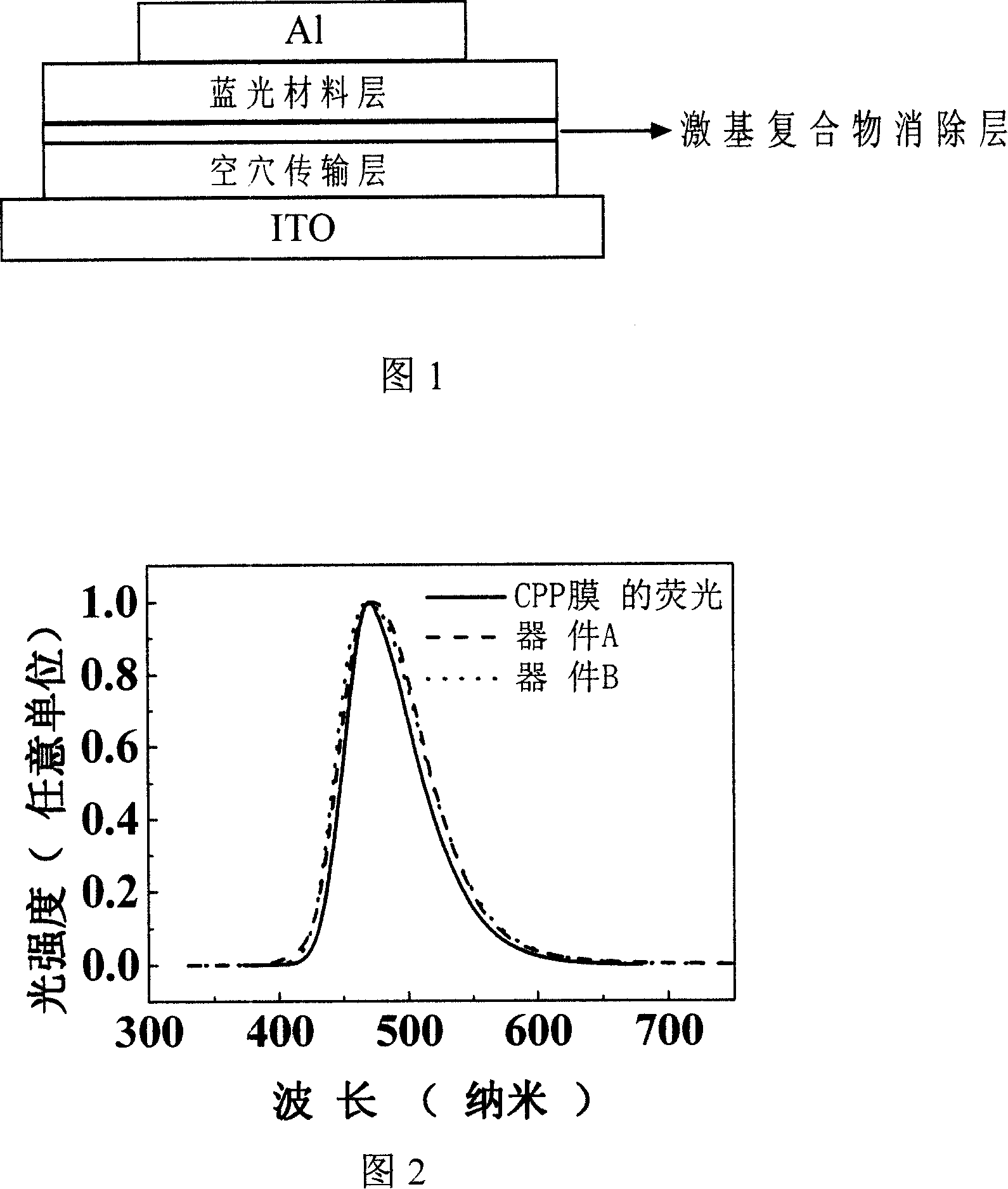
[0038] 1. The device structure includes: ITO anode, hole transport layer (HTL), exciplex elimination layer, electron acceptor material layer (EML) emitting blue light, and metal cathode.

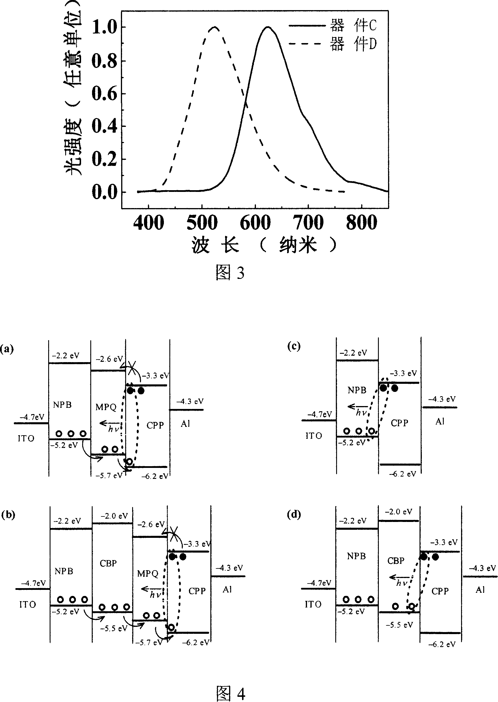
[0039] 2. The blue light-emitting material is an electron acceptor material, which has a strong electron-absorbing ability, and is easy to combine with commonly used hole transport materials such as 4,4'-...

Embodiment 1

[0045] The anode used in the device is ITO, and the cathode is aluminum (Al), but the cathode is not limited thereto, and may also be metals such as lithium, calcium, barium, magnesium, and silver. The structure of the constructed device is shown in Figure 1.

[0046] Implementation steps:

[0047] The first step: cleaning of ITO glass

[0048] The ITO glass was washed with detergent, tap water, deionized water, acetone, and absolute ethanol in sequence, and then dried in an oven.

[0049] Step 2: Evaporate the organic layer

[0050]Place the ITO glass piece in the vacuum chamber, at 4×10 -4 Under the vacuum condition of Pa, each organic layer is deposited at a rate of 1 Ȧ / s, and the evaporation sequence is the hole transport layer, the exciplex elimination layer, and the blue light material layer. For the reference device, no evaporated exciplex removal layer is required.

[0051] Step 3: Cathode Preparation

[0052] An Al cathode is evaporated on the ITO substrate on w...


PUM


Abstract

A preparation method of the blue organic light-emitting diode based on the electron acceptor materials, comprising the following steps. I. A hole transport material is vapor-plated on the glass substrate of In-Tin Oxide; II. The exciplex eliminating material is vapor-plated on the hole transport material layer; III. The blue luminescent material of strong electron withdrawing ability is vapor-plated on the exciplex eliminating material; IV. The cathode material is vapor-plated on the blue luminescent material. The blue luminescent material is the electron acceptor material with strong electron withdrawing ability. The invention inserts an exciplex eliminating material between the hole transport layer and the luminescence layer of the electron acceptor material to separate the mutual action of the electron donor and the electron acceptor, so as to inhibits the formation of the exciplex and avoids the new emission peak along the long wavelength direction emitted from the light-emitting devices; meanwhile, the molecular of the material possesses the suitable energy level for transmission and composition of the carrier, thereby improving the luminous brightness and efficiency of the device.

Description

technical field [0001] The invention relates to a preparation method of a light-emitting diode, in particular to a preparation method of a high-efficiency blue light organic light-emitting diode based on an electron acceptor material with strong electron-absorbing ability. Background technique [0002] Organic Light Emitting Diodes (OLEDs) have made considerable progress since they were reported in 1987 (C.W. Tang, S.A. VanSlyke, Appl. Phys. Lett. 1987, 51, 913) due to their potential applications in display and lighting . For full-color display applications, red, green, and blue materials are required, and efficient blue light materials are particularly important, because other colors can be obtained by down-converting the energy of blue light. Although many blue-light materials have been reported, these blue-light materials have weak electron transport and injection capabilities, so they must be doped into host materials with better electron transport capabilities, or an ...

Claims


Application Information

Patent Timeline
IPC IPC(8): H01L51/56H01L51/54H01L51/50
Inventor 于贵徐新军陈仕艳刘云圻狄重安朱道本
Owner INST OF CHEM CHINESE ACAD OF SCI
Why Eureka
Try Eureka