Device for separating ice and crystal

A separation device and ice crystal technology, applied in other dairy products, dairy products, food preparation, etc., can solve the problems of slow ice crystal discharge, poor ice crystal separation effect, high content, etc., to reduce solute loss, save energy consumption, improve separation efficiency effect

Inactive Publication Date: 2008-02-27
陈锦权
View PDF1 Cites 9 Cited by
  • Summary
  • Abstract
  • Description
  • Claims
  • Application Information

AI Technical Summary

Problems solved by technology

But this device has the following problems: 1. The ice crystals in the crystallization tank are pumped into the ice crystal growth tank and the whole tank is stirred to consume a lot of energy, and due to the centripetal force generated by the rotation, most of the ice crystals are clamped between the tank wall and the outlet In the annular area between, when there is no external force to push the ice crystals out of the outlet, the discharge speed of the ice crystals will be slow or even unable to be completely discharged, so the ice crystal separation effect is poor and the efficiency is low, and

Method used


Image

  • Device for separating ice and crystal
  • Device for separating ice and crystal
  • Device for separating ice and crystal

Examples


Embodiment 1

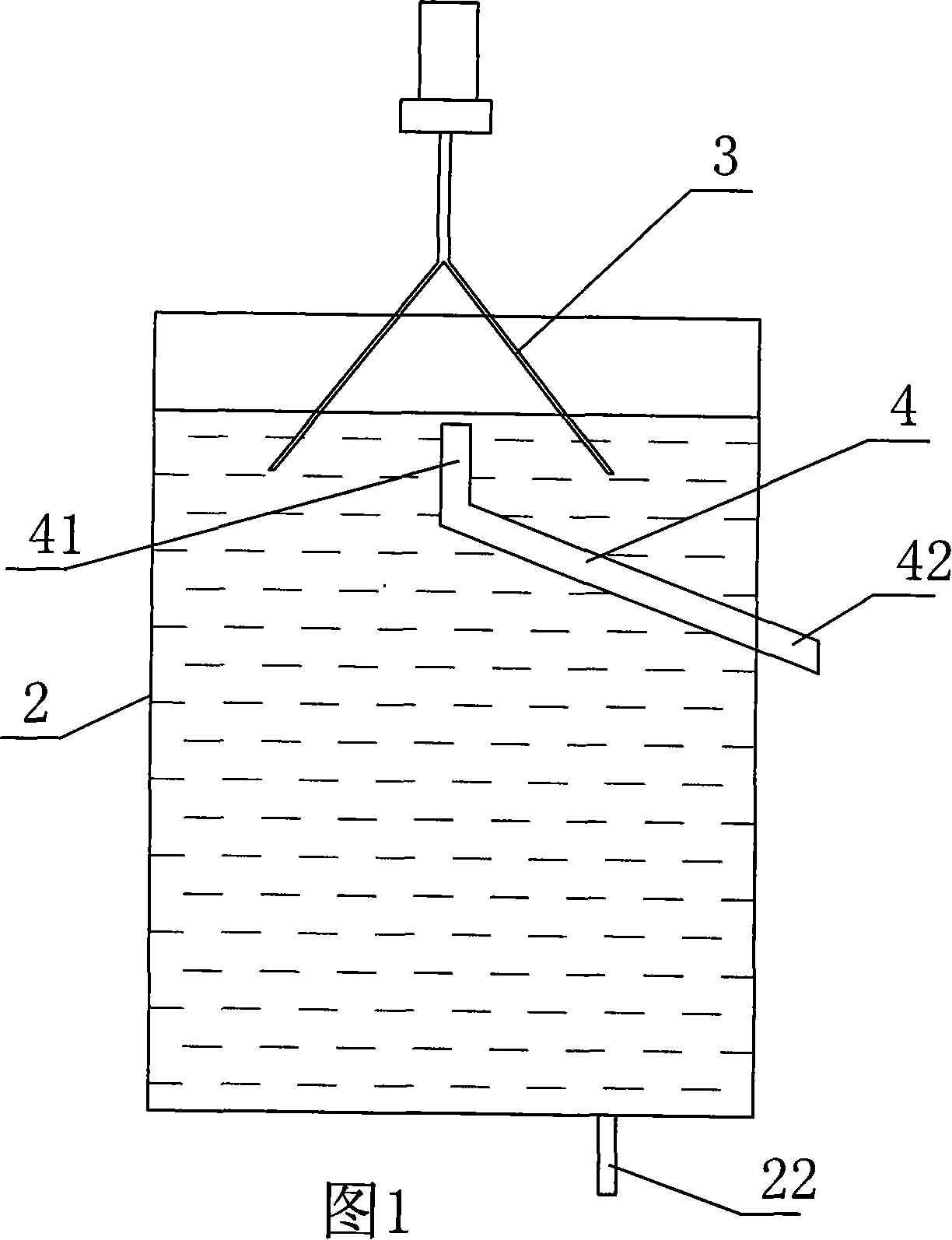
[0025] As shown in Figure 1, it is a schematic diagram of the structure of Embodiment 1 of the present invention, which includes a tank body 2 for holding ice crystals and liquid mixture materials, and is characterized in that: the upper part of the tank body is provided for rotating the liquid surface in the tank body. A moving surface stirrer 3, the surface stirrer is in a bifurcated shape, so that when the surface of the liquid is rotated, the ice crystals with a lighter density can gather towards the center under the action of the centripetal force generated by the rotation; the tank is also equipped with Hollow ice crystal collecting pipe 4, the ice crystal collecting port 41 of the ice crystal collecting pipe is located in the rotating center of the liquid level in the tank, and the ice crystal discharge port 42 leads to the outside of the tank body.

[0026] The opening of the ice crystal collecting port faces upward.

[0027]The ice crystal discharge port protrudes fro...

Embodiment 2

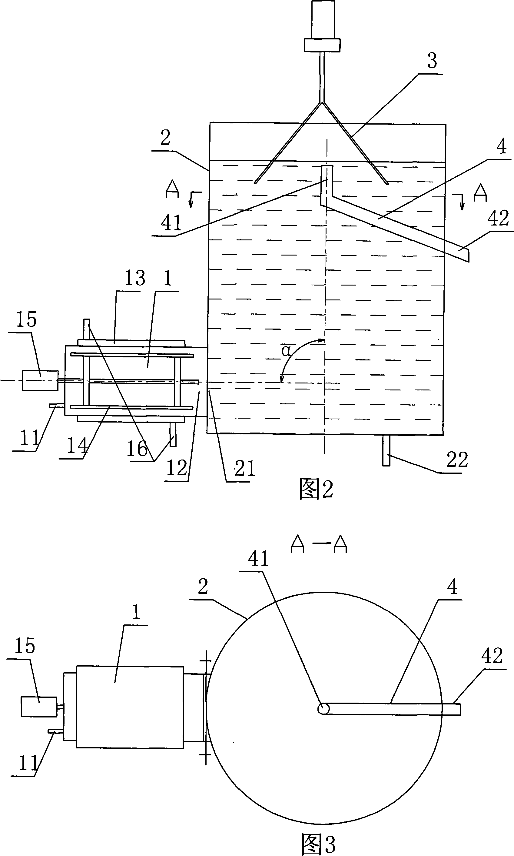
[0031] As shown in Figure 2 and Figure 3, it is a schematic diagram of the structure of Embodiment 2 of the present utility model. The difference between Embodiment 2 and Embodiment 1 is that the bottom of the ice crystal growth tank is provided for connecting with the material outlet 12 of the scraper heat exchanger 1 The material inlet 21, the outer periphery of the heat exchanger is provided with an interlayer 13 for the circulation of the refrigerant, and the inside is provided with a scraper 14 for scraping off ice crystals adhering to the inner wall. The tank wall between the interlayer and the inner cavity of the tank constitutes the heat exchange surface between the refrigerant and the material in the tank. Due to the low temperature of the heat exchange surface, ice crystals can be rapidly formed on the surface of the material in direct contact with the heat exchange surface. The scraper 14 is controlled by the driving device 15 and rotates slowly in the heat exchanger...

Embodiment 3

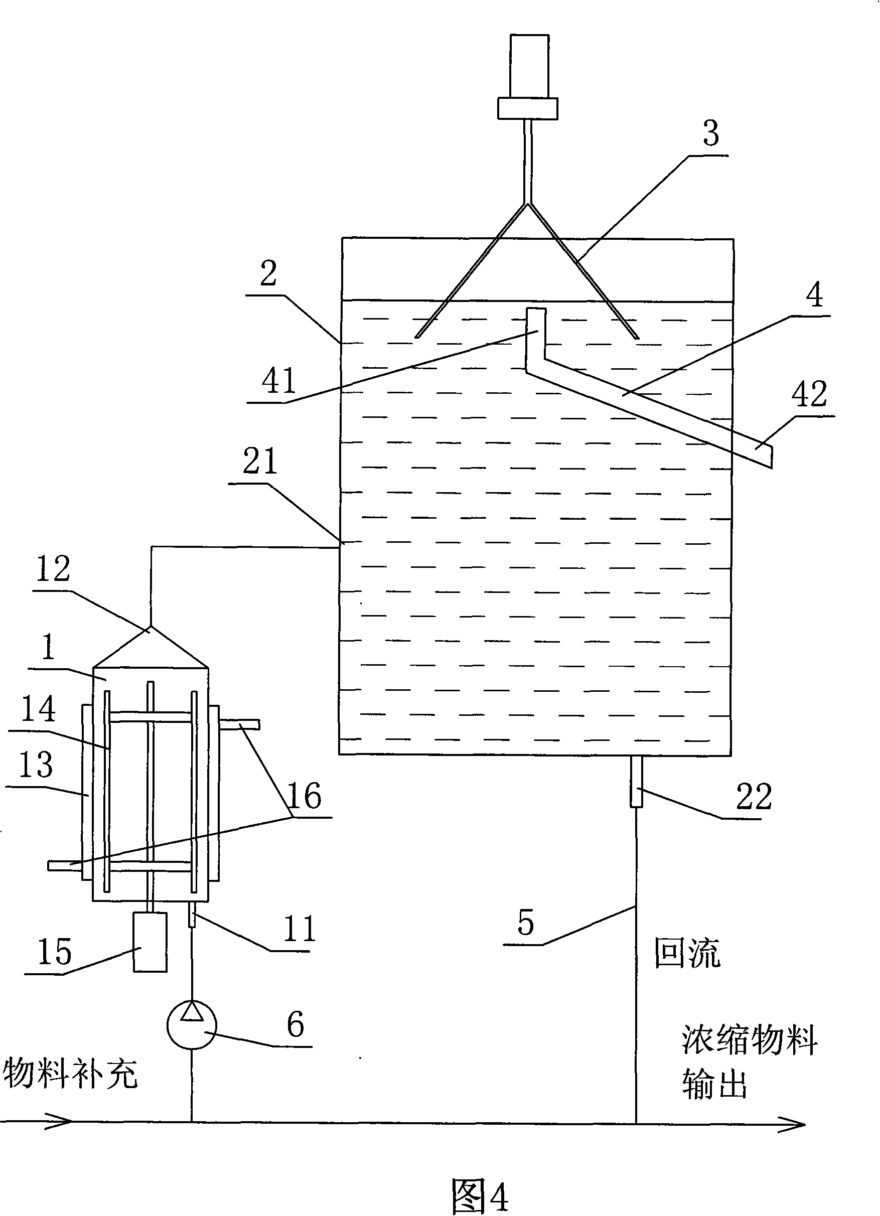
[0035] As shown in Figure 4, it is a schematic diagram of the structure of Embodiment 3 of the present invention. The difference between Embodiment 3 and Embodiment 2 is that: the scraper heat exchanger and the ice crystal growth tank are set independently, and the material outlet of the heat exchanger passes through a pipeline. It is connected with the bottom of the ice crystal growth tank, and the bottom of the ice crystal growth tank is also provided with another return pipe 5 connected to the material inlet of the heat exchanger. Openable and closed pumping device 6 for recrystallization in the heater.


PUM


Abstract

The invention relates to a cryolite separating arrangement, which comprises a tank for putting the cryolite and the liquid mixture material, wherein the top of the tank is equipped with the surface agitator for making the liquid surface rotate, the surface agitator is the bifurcation shape, the tank is also equipped with the hollow cryolite collecting pipe, the cryolite collecting port of the cryolite collecting pipe is at the central position of the liquid surface rotating, and the discharge port of the cryolite vents to the exterior of the tank. The invention makes the cryolite move to the liquid surface rotating center of the cryolite collecting port naturally with the cryolite buoyance and centripetal force produced by mixing the liquid surface and discharge by the cryolite collecting pipe (that is also the center or centripetal discharging cryolite method), which not only saves the energy and improves the separation efficient, but also reduces the loss of solute and is fit for the concentration industry production by freezing.

Description

technical field [0001] The invention relates to an ice crystal separation device, which is a separation device for separating ice crystals and liquid in a mixture of ice crystals and liquid. The device can be widely used in liquid foods such as fruit and vegetable juices, milk, tea juice, and traditional Chinese medicine. The ice crystal and liquid separation process in the freeze concentration process of the extract. Background technique [0002] Concentration is an important unit operation in liquid food processing. There are mainly three methods: evaporation, reverse osmosis, and freeze concentration. Freeze concentration is a concentration method that uses the principle of solid-liquid phase equilibrium between ice and aqueous solution. Its operation is to cool the dilute solution below the freezing point (freezing point) of water to freeze part of the water into ice crystals, and separate the ice crystals to obtain a concentrated solution. . [0003] In industry, ther...

Claims


Application Information

Patent Timeline
IPC IPC(8): A23L2/04A23C1/06A23F3/18A23L1/28A23L33/00A23L33/10A23L33/105
Inventor 陈锦权方婷
Owner 陈锦权
Why Eureka
Try Eureka