A method for vacuum scattering and joining-up carbon-carbon composite material

A carbon composite material and vacuum diffusion technology, applied in the field of carbon/carbon composite material welding, can solve the problems of poor joint performance, large metal deformation and high connection temperature

Inactive Publication Date: 2008-04-16
HARBIN INST OF TECH
View PDF0 Cites 3 Cited by
  • Summary
  • Abstract
  • Description
  • Claims
  • Application Information

AI Technical Summary

Problems solved by technology

[0003] The purpose of the present invention is to provide a method for vacuum diffusion bonding carbon/carbon composite materials in order to solve the problems of hig

Method used


Image

  • A method for vacuum scattering and joining-up carbon-carbon composite material
  • A method for vacuum scattering and joining-up carbon-carbon composite material

Examples


specific Embodiment approach 1

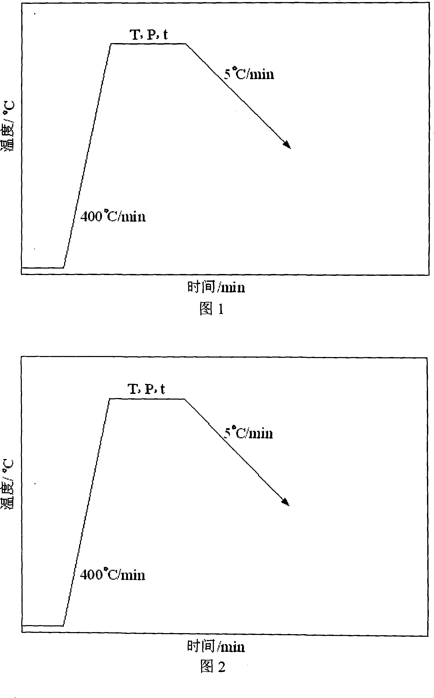
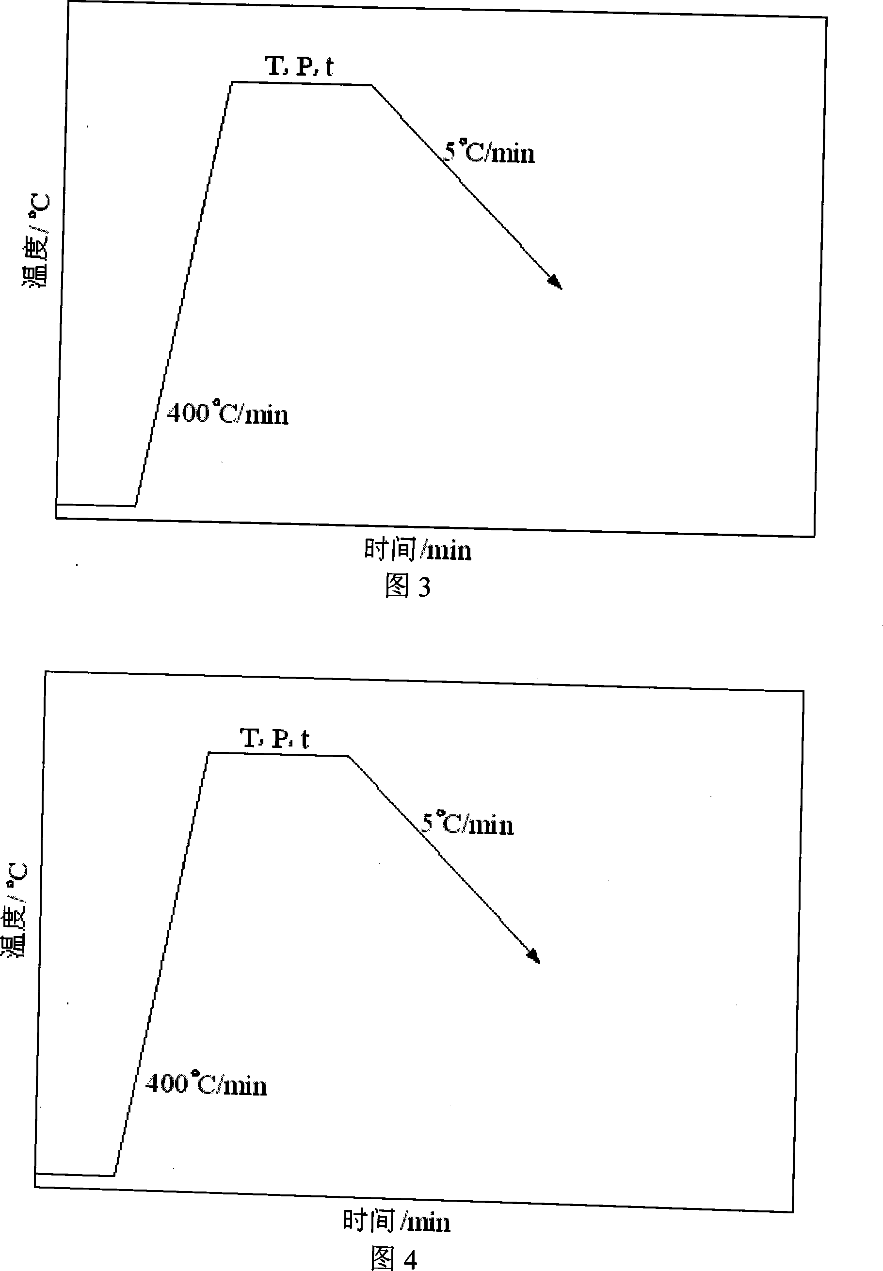
[0008] Specific Embodiment 1: In this embodiment, a method for vacuum diffusion bonding carbon / carbon composite materials is implemented according to the following steps: 1. Clean the surface of the base metal before diffusion bonding; 2. Place the diffusion intermediate layer evenly on the base material to be welded The connection surface of the material; the middle layer of the diffusion connection is a hydrogenated titanium or titanium alloy foil, and the thickness of the diffusion connection middle layer is 30-100 μm; 3. Place the clamped weldment in a vacuum diffusion welding machine for heating. Vacuum degree is 1.33×10 -3 ~4.0×10 -3 Diffusion connection is carried out under Pa vacuum condition; 4. After welding, the weldment is depressurized when the original vacuum condition drops to 100°C, and the weldment is taken out when the temperature is lowered to room temperature.

[0009] In this implementation method, the diffusion bonding process parameters should adopt the...

specific Embodiment approach 2

[0010] Specific embodiment 2: The difference between this embodiment and specific embodiment 1 is that in step 1, the surface of the parent material is cleaned by physical cleaning, chemical cleaning or first physical cleaning followed by chemical cleaning; the physical cleaning is followed by 400 # 、500 # 、600 # , 800 # and 1000 # The metallographic sandpaper is polished step by step; the chemical cleaning is to prepare the corresponding corrosion solution according to the difference of the base metal to remove the adsorption layer, impurities or oxide film on the surface of the base metal, and then wipe the surface of the base metal to be welded with acetone or remove the base metal The materials were cleaned ultrasonically in acetone solution. Other steps and parameters are the same as those in Embodiment 1.

specific Embodiment approach 3

[0011] Embodiment 3: The difference between this embodiment and Embodiment 1 is that the thickness of the diffusion-connected intermediate layer in step 2 is 30-80 μm. Other steps and parameters are the same as those in Embodiment 1.


PUM

PropertyMeasurementUnit
Thicknessaaaaaaaaaa
Thicknessaaaaaaaaaa
Thicknessaaaaaaaaaa

Abstract

A vacuum diffusion connecting carbon/carbon composite material method belongs to the welding field of the carbon/carbon composite material. The present invention settles the problems of high jointing temperature, large metal deformation of the partial part of joint and inferior joint capability in the existing diffusion connecting carbon/carbon composite material. The invention comprises the following steps: 1. doing cleaning to the surface of the base metal; 2. homogeneously parking the diffusion middle layer to the connecting surface of the base metal to be welded; 4. reducing temperature then the welded component which is connected well is obtained. The diffusion connecting carbon/carbon composite material of the invention is reduced by 100 to 300 DEG C, the shear strength of the diffusion connecting between the carbon/carbon composite material and the carbon/carbon composite material or the carbon/carbon composite material to other metal material is increased by 20 to 220 percent, and the metal at the joint has no evident shape change.

Description

technical field [0001] The invention belongs to the field of welding of carbon / carbon composite materials, and is applicable to the connection of carbon / carbon composite materials and other dissimilar materials. Background technique [0002] Carbon / carbon composites have a low density (about 2.0g / cm 3 ), light weight, high modulus, high specific strength, low thermal expansion coefficient, high temperature resistance, thermal shock resistance, corrosion resistance, good vibration absorption, etc., are extremely important for future defense, aerospace competition and development. When carbon / carbon composite materials are applied in engineering, they need to be made into components, which inevitably encounter welding problems, including their own welding and welding with other materials. The special crystal structure and physical and chemical properties of carbon / carbon composites make their connection difficult. First, the chemical structure of carbon / carbon composites is s...

Claims


Application Information

Patent Timeline
IPC IPC(8): B23K20/16B23K20/24
Inventor 何鹏冯吉才刘宏王伦王明
Owner HARBIN INST OF TECH
Why Eureka
Try Eureka