
Waste gas treatment equipment with aeration groove of biological purification tower

A technology of waste gas treatment equipment and purification tower, which is applied in the direction of air quality improvement, chemical instruments and methods, and separation of dispersed particles. It can solve the problems of large investment, high energy consumption, and incomplete treatment, and achieves convenient operation and management. The effect of small area and compact structure

Inactive Publication Date: 2008-05-07
北京中盛泓源科技有限公司
View PDF0 Cites 11 Cited by
  • Summary
  • Abstract
  • Description
  • Claims
  • Application Information

AI Technical Summary

Problems solved by technology

[0009] The purpose of the present invention is to propose a new biological purification tower treatment equipment, which overcomes the defects of large investment, high energy consumption, and incomplete treatment in the conventional waste gas treatment methods of the petrochemical industry, and can effectively remove the waste gas in the petrochemical industry. Toxic, high-concentration, and biodegradable waste gas is thoroughly treated, which solves the problem of environmental pollution caused by organic waste gas and personal injury to on-site operators

Method used


Image

  • Waste gas treatment equipment with aeration groove of biological purification tower

Examples


Embodiment Construction

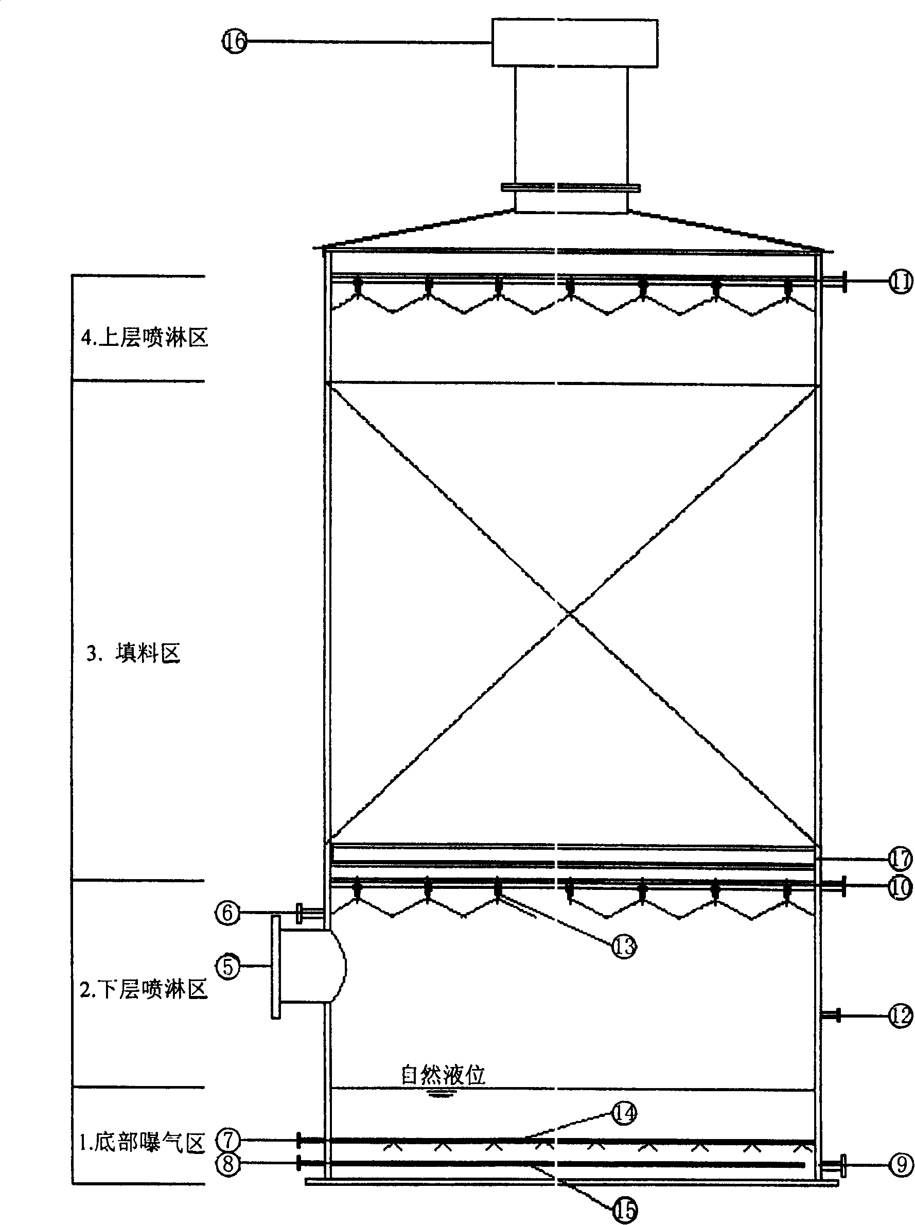
[0033] The biological purification tower equipment is made of carbon steel structure, and the inner wall is lined with rubber for anticorrosion. The diameter of the tower body is 4 meters, the height is 8 meters, and the total volume is 100 cubic meters. The equipment is equipped with 14 perforated aeration pipes and 15 steam heating tubes at the bottom The coil consists of 1 bottom aeration tank, 2 lower spray areas equipped with spiral nozzles, 4 upper spray areas and 3 packing areas.

[0034] There are 7 air inlets, 8 steam inlets, and 9 mixed liquid outlets on the side wall of the aeration zone at the bottom of the equipment. The entrance is connected; the side wall of the 2nd lower layer of the equipment is equipped with 5 exhaust gas inlets, 10 lower layer spray liquid inlets, 6 nutrient solution inlets, and 12 clean water inlets, which are respectively connected to the outlet of the induced draft fan outside the tower and the circulation pump outside the tower. The outl...


PUM

PropertyMeasurementUnit
Diameteraaaaaaaaaa

Abstract

The invention relates to a waste gas treatment device for treating the gas which is difficult to be degraded biologically and generated by a petrochemistry industry production site and a wastewater treatment field by utilizing special effective microorganism, in particular to a combined type biological purification tower, which integrates all advantages of a biological filtration tower and an aeration tank, and realizes the degradation to the waste gas by depending on the special effective microorganism and the special nutrient solution. The device is composed of four main areas of a bottom part aeration area, a lower layer spaying area, a filling area and an upper layer spaying area, the mixed liquid in the bottom part aeration area returns to the tower via a circulation pump through the upper layer spaying area and the lower layer spaying area, and spiral nozzles are arranged both in the upper layer spaying area and the lower layer spaying area; after the waste gas enters the tower through an induced draft fan, the hydrophilic organic pollutant thereof is trapped when getting through the lower layer spaying area, and is degraded through depending on the microorganism at the bottom part, the volatile organic compound is adsorbed and degraded by the biofilm adhered on the filing material when getting through the filling area, and the purified waste gas is exhausted through an exhaust opening arranged at the top part, thereby reducing the pollution to the surrounding environment.

Description

technical field [0001] The invention belongs to waste gas treatment equipment for treating refractory biodegradable waste gas produced in the petrochemical industry by using special-effect microorganisms and nutrient solution, and particularly relates to a combined biological purification tower equipment. Background technique [0002] In the process of production and wastewater treatment in the petrochemical industry, some volatile organic waste gases will be produced. The common characteristics of these waste gases are that they are toxic and difficult to biodegrade. They must be purified before being discharged into the atmosphere, otherwise they will pollute the surrounding environment and cause direct harm to the human body. Commonly used treatment methods for these organic waste gases include activated carbon adsorption method, incineration method, catalytic oxidation method, cooling concentration method, biological treatment method, etc. The characteristics of the abov...

Claims


Application Information

Patent Timeline
IPC IPC(8): B01D53/84
CPCY02A50/20
Inventor 徐森黄志杰党政吴建华
Owner 北京中盛泓源科技有限公司
Learn More