Low-power consumption wireless receiver radio frequency front end circuit

A wireless receiver, RF front-end technology, applied in electrical components, sustainable buildings, transmission systems, etc., can solve the problems of large number of on-chip inductors, large chip area, design difficulty and cycle increase

Inactive Publication Date: 2008-05-21
FUDAN UNIV
View PDF0 Cites 27 Cited by
  • Summary
  • Abstract
  • Description
  • Claims
  • Application Information

AI Technical Summary

Problems solved by technology

The disadvantage of this is that the two parts of the circuit affect each other, and the design needs to go through the process of separate design, simulation to interconnection, joint simulation, and parameter modification, which increases the difficulty and cycle of design.
Difficulties in the design of the two-part circuit interface lead to insufficient optimization of the perf...

Method used


Image

  • Low-power consumption wireless receiver radio frequency front end circuit
  • Low-power consumption wireless receiver radio frequency front end circuit
  • Low-power consumption wireless receiver radio frequency front end circuit

Examples


Embodiment Construction

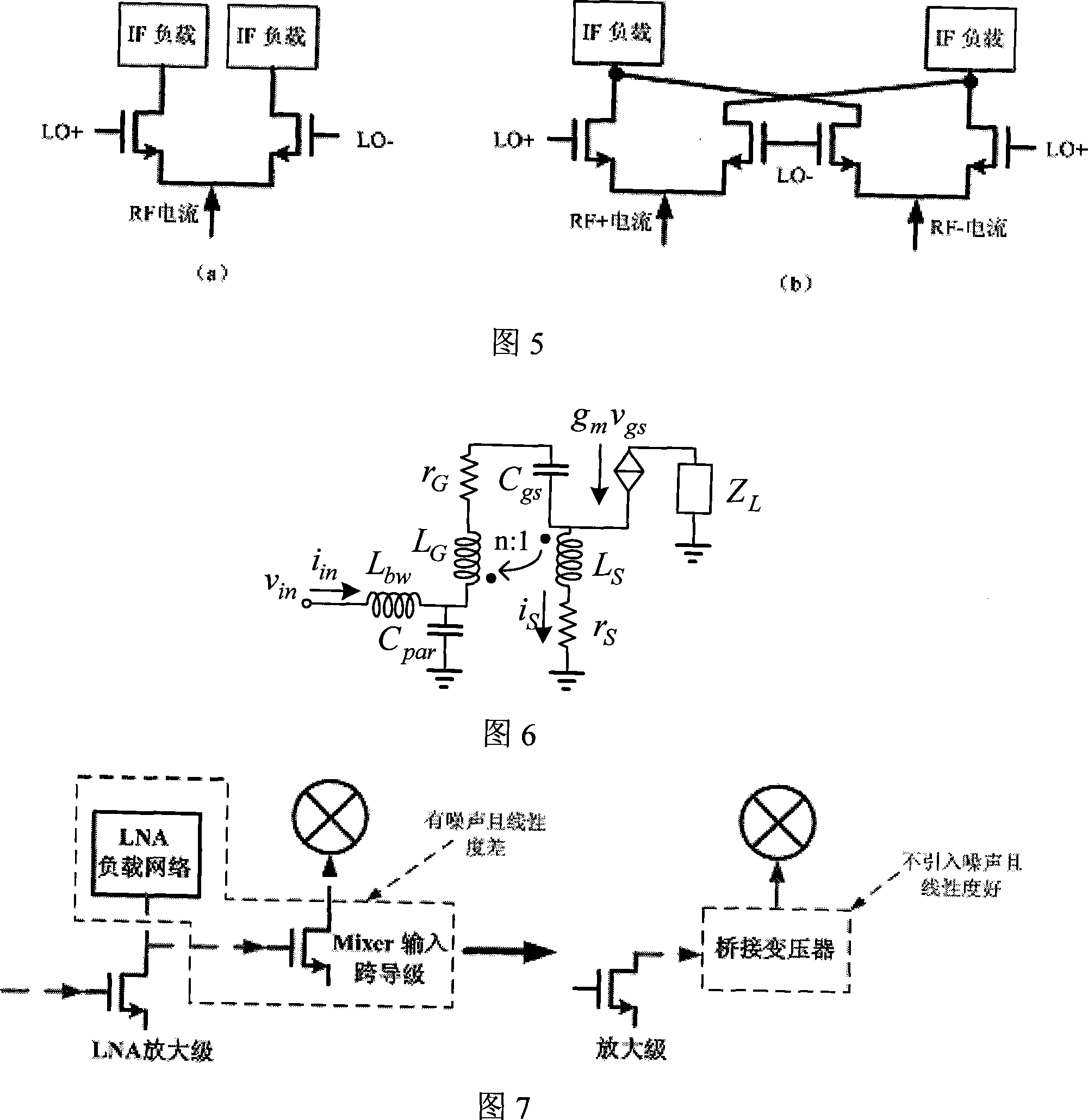
[0055] The RF front-end structure is applied to the fully differential RF front-end circuit of the MB-OFDM UWB RF receiver in the 3.1GHz to 4.7GHz frequency band, and the specific design parameters are shown in Figure 8. Using 0.18um RF CMOS 1P6M process, the simulation tool is Cadence SpectreRF, where V B1 = 0.82V, V B2 =0.68V, the grid bias voltage of the main amplifier tube M1 / 2 of the RF amplifier stage is 1.08V, and the grid bias voltage of the LO switch stage tube is 0.8V.

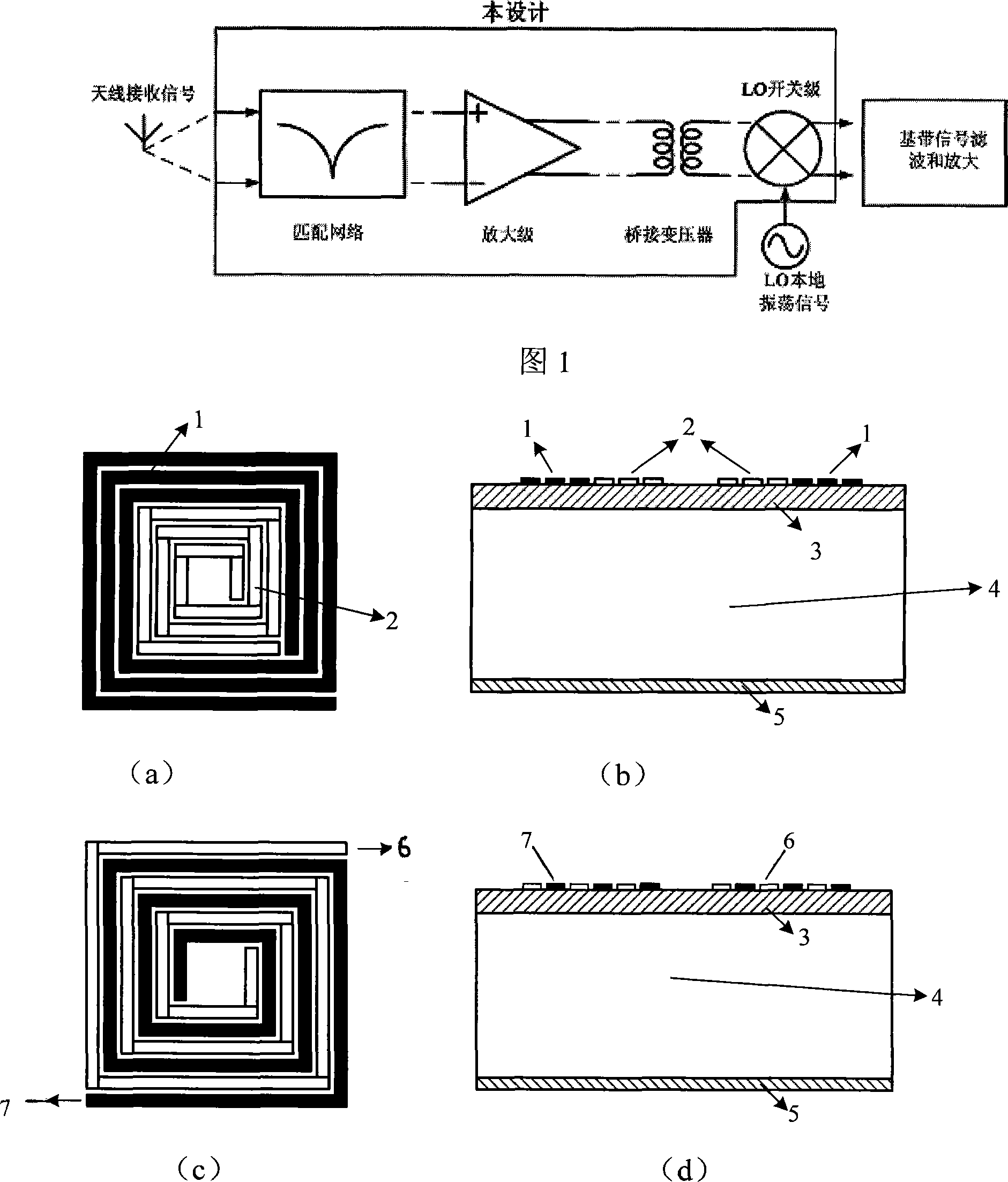
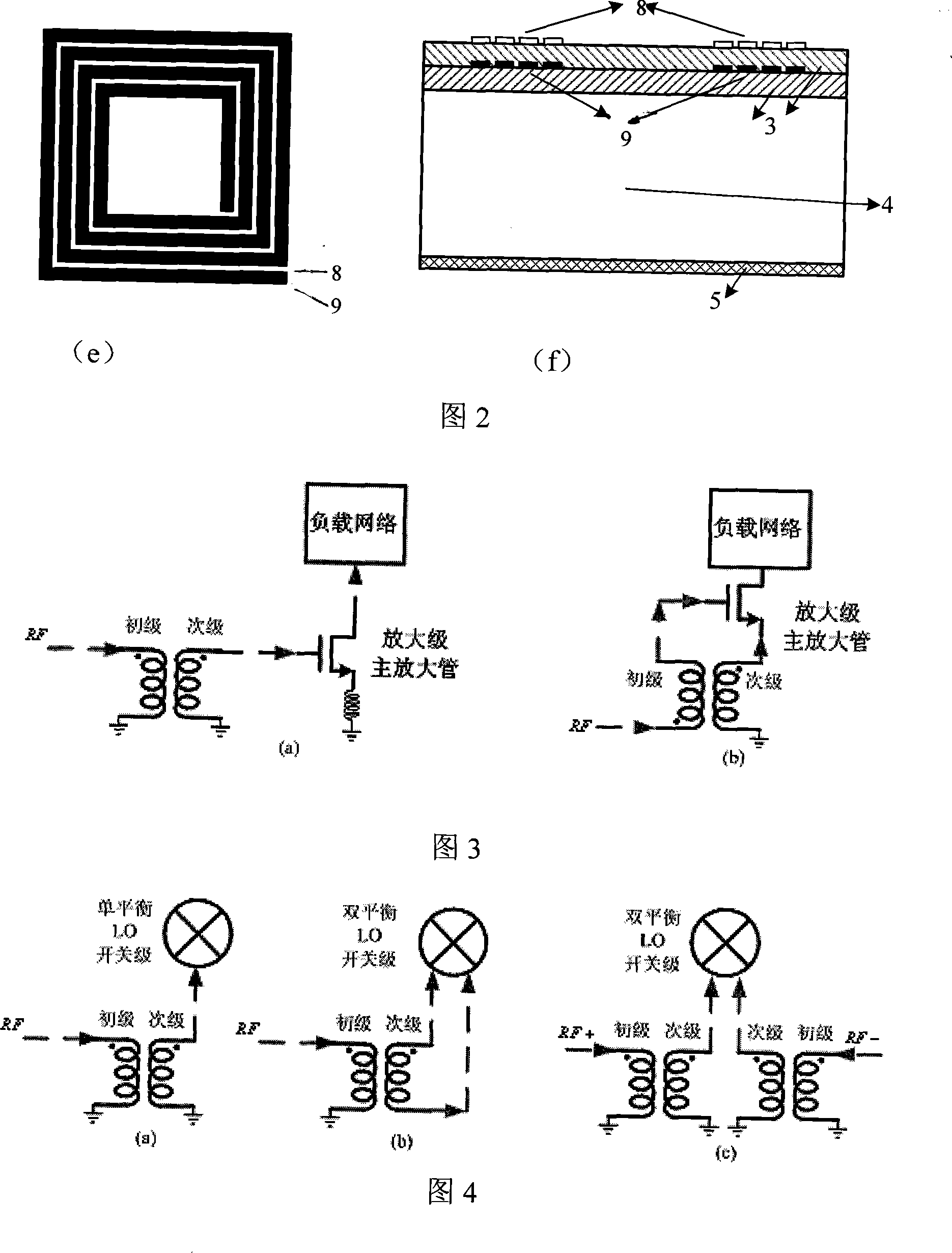
[0056] The transformer used in the input matching network is a tapped planar on-chip transformer, the sixth layer of metal wiring, the inductance value of the primary coil is 3.5nH, the inductance value of the secondary coil is 0.8nH, the turns ratio is 1:0.48, and the coupling coefficient is about 0.4 ; The bridge transformer adopts a cross-type planar on-chip transformer, the sixth layer of metal wiring, the primary and secondary coils are 2n, that is, the turns ratio is 1:1, and the coupling coef...


PUM


Abstract

The invention relates to a low power consumption RF front-end circuit of the wireless receiver, belonging to the technical field of the integrated circuit of the RF wireless receiver, , comprising an RF input matching network, an amplifier stage, a bridge transformer, an LO switch stage, an IF load and a current source bias circuit; wherein, the RF input matching network implements the impedance matching between an antenna and the amplifier stage; the amplifier stage is used for amplifying the signal, the bridge transformer transfers the signal amplified to the LO switch stage and implements DC isolation between the front stage and back stage; the LO switch stage is used for implementing frequency mixing of the RF current signal and the LO signal and outputting alternatively the IF signalon an outputting differential load. Compared with the traditional RF front-end circuit, the circuit structure can use an on-chip integrated transformer or an on-chip inductor to implement inputting matching, and use the on-chip integrated transformer to implement the amplifying and downward frequency mixing of the RF signals perfectly, which simplifies the circuit structure. The circuit can be used in a low power supply voltage environment, and has the advantages of low DC power consumption, and less circuit noise and signal distortion.

Description

technical field [0001] The invention belongs to the technical field of radio frequency wireless receiver integrated circuits, and in particular relates to a radio frequency front-end circuit (RF Front-end) used in wireless receiver integrated circuits. It can be used for radio frequency signal receiver chips of technical standards such as broadband wireless network and high-speed wireless data transmission, such as WiMax and UWB. Background technique [0002] With the development of communication and semiconductor technology, various mobile communication systems and wireless data transmission technologies have developed rapidly. Representatives of them include GSM, CDMA, Bluetooth and WiFi, etc., especially in recent years 3G, IEEE802.11a / b / g , WiMax and UWB ultra-wideband technology and other high data rate wireless transmission technologies continue to emerge, which put forward high requirements for high-performance radio frequency signal receivers. Due to the high carrie...

Claims


Application Information

Patent Timeline
IPC IPC(8): H04B1/16H04B1/18
CPCY02B60/50
Inventor 李巍杨光
Owner FUDAN UNIV
Why Eureka
Try Eureka