LED lamp plate structure with patch type bracket and its production process

A technology of LED light board and production process, which is applied to the parts of lighting devices, semiconductor devices of light-emitting elements, lighting and heating equipment, etc., and can solve the problems of aging of phosphor powder, deterioration of color temperature stability of white light diodes, heat dissipation area of ​​bracket 1 Limited and other problems, to achieve the effect of good color temperature consistency, excellent heat dissipation effect, and excellent product quality

Inactive Publication Date: 2008-05-28
CHANG HSIN HIGH INTENSITY LED DONG GUAN
View PDF0 Cites 31 Cited by
  • Summary
  • Abstract
  • Description
  • Claims
  • Application Information

AI Technical Summary

Problems solved by technology

[0003] Referring to Fig. 1, the current light-emitting diode or LED lamp is composed of a two-legged support 1 (or positive and negative pins) and a chip 2 in a bowl on the support 1, covering the fluorescent powder on the chip 2. 4 and the epoxy resin 5 that encapsulates the chip 2, the chip 2 is connected to the support 1 through its positive and negative lead wires 3 respectively, its disadvantages: one is that the support 1 is a wire support, and its thermal conductivity is poor, and the light and heat emitted by the chip 2 make Phosphor powder 4 accelerates aging, which leads to poor color temperature stability of white light diodes and reduced product life; second, mechanized production cannot be realized. General LED l

Method used


Image

  • LED lamp plate structure with patch type bracket and its production process
  • LED lamp plate structure with patch type bracket and its production process
  • LED lamp plate structure with patch type bracket and its production process

Examples


Embodiment 1

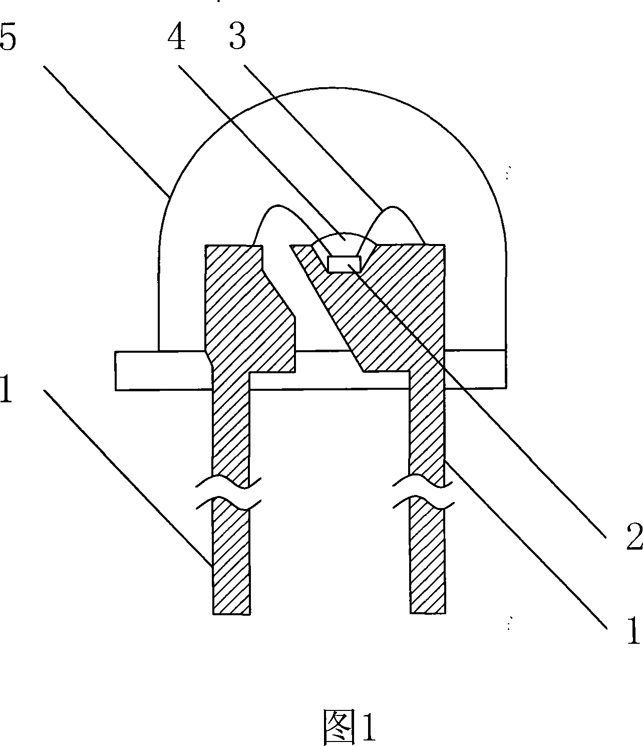
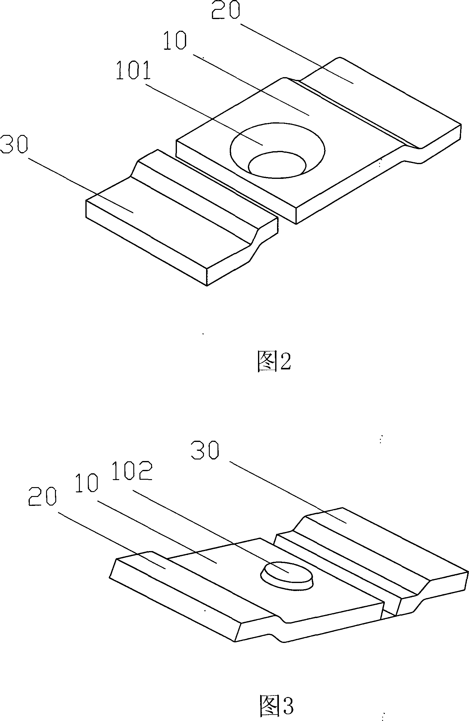
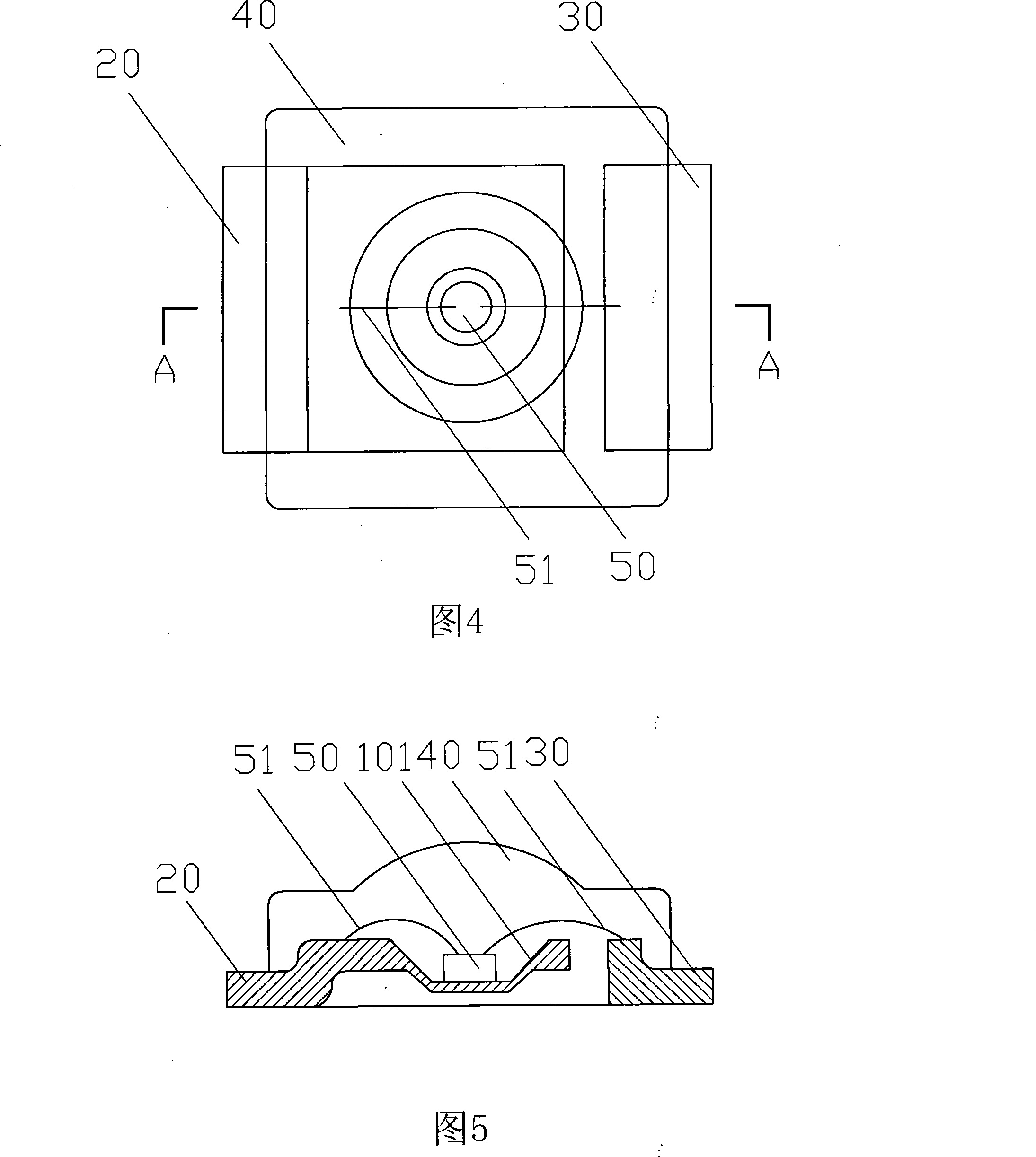
[0054]Embodiment 1: Refer to Fig. 2-5, Fig. 15-16: LED lamp board structure and its production process with patch bracket, which is characterized in that two metal plates that are not electrically connected to each other are used as the positive and negative poles of the LED lamp The connection terminals 20, 30 are arranged in the same plane, and a cup-shaped groove 101 is punched in the center on one of the pole plates 20, and the LED chip 50 is arranged in the middle of the groove 101, and the positive and negative poles 51 of the LED chip 50 They are respectively electrically connected to the metal plate terminals 20 and 30, and a solid or hollow transparent cover 40 is provided outside the LED chip 50, and a layer of phosphor powder may or may not be provided between the LED chip 50 and the transparent cover 40. After the LED chip 50 of the LED lamp is partially arranged in the center of the through hole 61 on the substrate 60, the positive and negative terminals 20, 30 of ...

Embodiment 2

[0066] Embodiment 2: Refer to Fig. 6-9, Fig. 17-18: the basic structure, production process and product use of this embodiment are the same as those of Embodiment 1, the difference is that each of the two metal plate terminals is connected 20 , 30 respectively extend to both sides to form a positive dual terminal 20 and a negative dual terminal 30. This structure is suitable for manufacturing medium-power or high-power LED lamps or lamp panels, because the positive dual terminal 20 and the negative dual terminal 30 are connected to the substrate. After 60 soldering, it is convenient to quickly dissipate the heat generated by the LED chip 50 in a larger amount during operation, so as to maintain a stable and long-term working state of the product.

Embodiment 3

[0067] Embodiment 3: Refer to Figures 10-14 and Figures 19-25: the basic structure, production process and product usage of this embodiment are the same as those of Embodiment 1, the difference is that a bottom of the cup-shaped groove 101 is punched into a Through hole 102, and both sides of through hole 102 are all set as bowl cup shape groove, like this, after LED chip 50 is packaged on the bowl cup shape groove 101 that has through hole 102, LED chip 50 is in groove 101 Both sides of the LED lamp can emit light, and can be made into a double-sided LED lamp 70 and an LED lamp board 80. This structure is a double-sided LED lamp 70 or LED lamp board 80 with large, medium and small power.

[0068] Extend each piece of terminal 20, 30 of the two metal plate terminals in Embodiment 3 to form a positive dual terminal 20 and a negative dual terminal 30 respectively, and then a medium-power or high-power LED lamp can be manufactured. 70 or LED light board 80.


PUM


Abstract

The invention relates to the light-emitting diode (LED) technology field, namely an LED lamp plate structure with a bonded holdfast and a productive technology. Two metal plates which are not mutually and electrically connected are used as the positive connecting terminal and the negative connecting terminal of an LED lamp, a bowl-cup-shaped groove with or without through-hole is punched on the middle of one of the polar plates, an LED chip is arranged on the middle portion of the groove, the positive polar and the negative polar of the LED chip are respectively connected electrically with the connecting terminals of the metal plates, a transparent cover is mounted on the outer side of the LED chip, a layer of fluorescent powder is arranged or is not arranged between the LED chip and the transparent cover, and the LED lamp is welded on a positive and negative metal layer of a PCB circuit of a base plate by a SMT automatic insertion bonding machine after integral light splitting. The invention has the advantages of excellent radiating effect, large light flux, long service life, low productive cost, and favorable compatibility of color-temperature, which can be used to produce various lighting lamps, light source modules, back light of an LED crystal display, etc.

Description

Technical field: [0001] The invention relates to the technical field of light-emitting diodes (LEDs), in particular to an LED lamp panel structure with a patch bracket and a production process thereof. Background technique: [0002] Light-emitting diode (LED) is a semiconductor solid light-emitting device. It uses a solid semiconductor wafer as a light-emitting material. When a forward voltage is applied to both ends, the carriers in the semiconductor recombine to cause photon emission to generate light. It is the most The popular light source technology, the characteristics of LED light source are: energy saving: energy consumption is reduced by 80% compared with incandescent lamps with the same light effect; using low voltage power supply (between 6-24V), good safety; small size, can be prepared into various Shaped devices; long life; fast response time: the response time of incandescent lamps is milliseconds, and the response time of LED lamps is nanoseconds; no harmful m...

Claims


Application Information

Patent Timeline
IPC IPC(8): F21V21/00F21V19/00F21V23/00H01L23/12H01L33/00F21Y101/02F21Y115/10G02F1/13357H01L33/48H01L33/62
CPCH01L2224/48247H01L2224/48257H01L2224/72H01L2224/8592H01L2924/181
Inventor 邹本壮
Owner CHANG HSIN HIGH INTENSITY LED DONG GUAN
Why Eureka
Try Eureka