
Method of electrolyzing wastewater containing ammonia nitrogen and apparatus therefor

A technology of electrolytic treatment and ammoniacal nitrogen, which is applied in water/sewage treatment, water treatment parameter control, water/sludge/sewage treatment, etc. It can solve the problems of difficulty in suppressing the generation of nitric acid, increase and decrease of operating costs, and achieve the goal of suppressing Effect of nitric acid generation reaction, improvement of ammonia decomposition efficiency, and improvement of ammonia removal efficiency

Active Publication Date: 2008-06-11
MITSUBISHI HEAVY IND ENVIRONMENTAL & CHEM ENG CO LTD
View PDF1 Cites 13 Cited by
  • Summary
  • Abstract
  • Description
  • Claims
  • Application Information

AI Technical Summary

Problems solved by technology

[0009] However, the method disclosed in Patent Document 1 has the following problems: it has almost no buffer capacity for the target wastewater, and a large amount of alkaline agent is required to adjust the pH to 8 to 12, resulting in increased operating costs
[0011] Furthermore, the existing electrolysis method has the problem that H + , causing a decrease in pH value, so chlorine gas volatilizes, and then the concentration of chloride ions in wastewater decreases, and the efficiency of chlorine generation decreases
Therefore, as disclosed in Patent Document 1, under the condition of having chloride ions, the pH value is controlled within the range of 8 to 12, and electrolytic treatment is carried out to suppress the reduction of the concentration of chloride ions, but it is difficult to suppress the generation of nitric acid, so it is not yet available. The reduction in current efficiency cannot be improved, which is the current situation

Method used


Image

  • Method of electrolyzing wastewater containing ammonia nitrogen and apparatus therefor
  • Method of electrolyzing wastewater containing ammonia nitrogen and apparatus therefor
  • Method of electrolyzing wastewater containing ammonia nitrogen and apparatus therefor

Examples


Embodiment 1

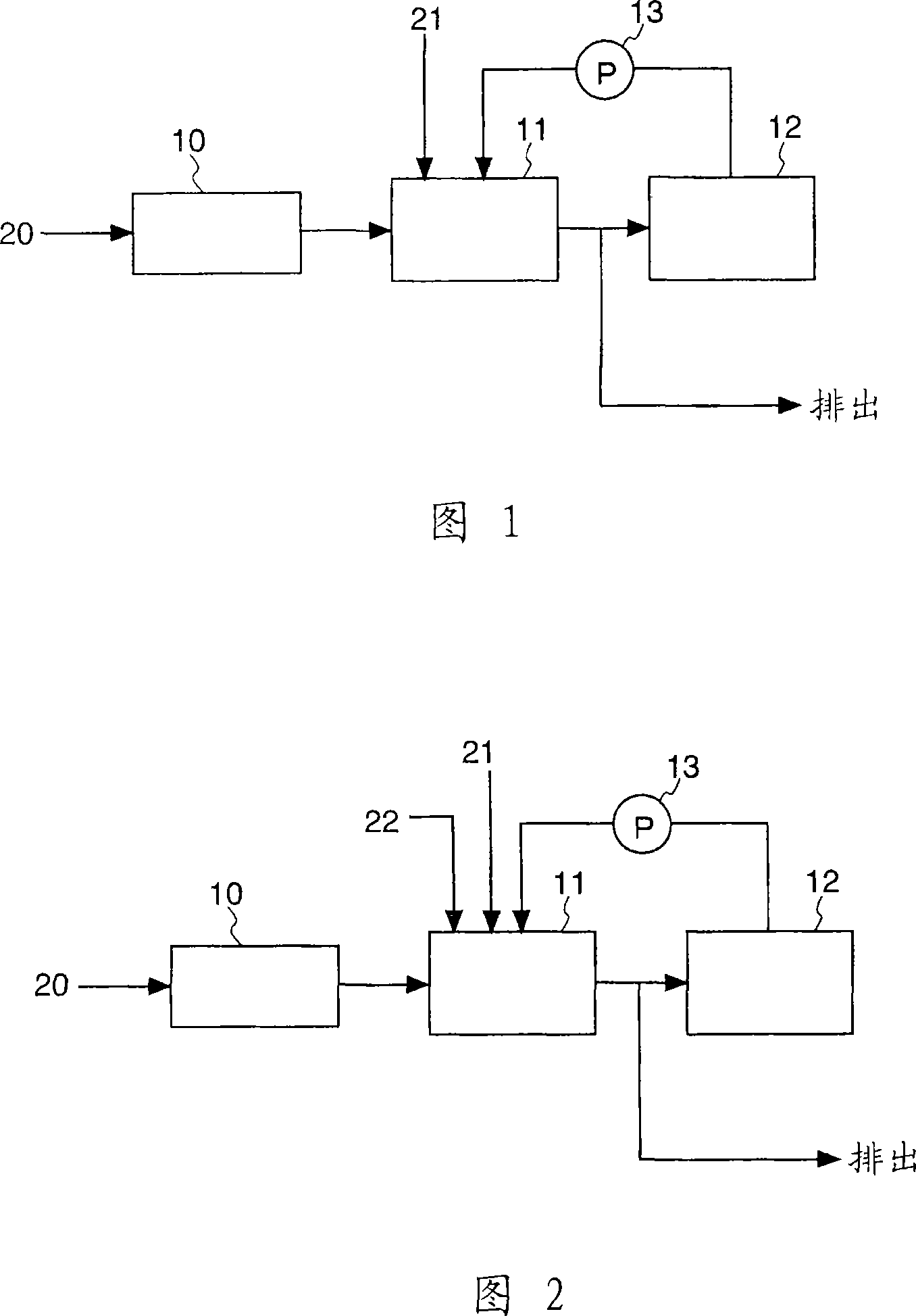
[0071] The treatment device of the present embodiment 1 shown in Fig. 1 comprises: deposit the raw water tank 10 that contains the waste water 20 of ammoniacal nitrogen, import the circulation adjustment tank 11 of the waste water 20 that flows out by this raw water tank, and import by circulation pump 13 from The electrolytic tank 12 for the conditioning solution of the circulation adjustment tank 11 ; and the electrolytic treatment solution treated in the electrolytic tank 12 is circulated in the circulation adjustment tank 11 .

[0072] The circulation adjusting tank 11 has a pH adjusting device, and is adjusted by adding a pH adjusting agent 21 so that the pH value of the treatment liquid in the tank is 5 or more and less than 8. The pH adjusting agent 21 can use an acid or an alkali agent, but in this embodiment, its structure is to circulate the electrolytic treatment solution from the electrolytic cell 12, so the pH value of the liquid is mainly biased toward the acid si...

Embodiment 2

[0091] FIG. 2 shows a schematic configuration diagram of a processing device related to the second embodiment. Hereinafter, in Embodiment 2 to Embodiment 8, a detailed description of the same configuration as in Embodiment 1 above will be omitted.

[0092] In addition to the structure of the above-mentioned embodiment 1, the present embodiment 2 is further provided with a reducing device for the electrolytic treatment solution. As the reduction device, it is preferable to use a device that supplies a reducing agent 22 to the circulation adjustment tank 11 as shown in FIG. 2 . As the above-mentioned reducing agent 22, well-known reducing agents such as sodium thiosulfate can be used.

[0093] In this way, by installing a reducing device in the system, excessively generated chlorine can be reliably decomposed, and the residue of chloramine or free chlorine can be suppressed. In addition, by suppressing the concentration of residual chlorine, it is possible to suppress the genera...

Embodiment 3

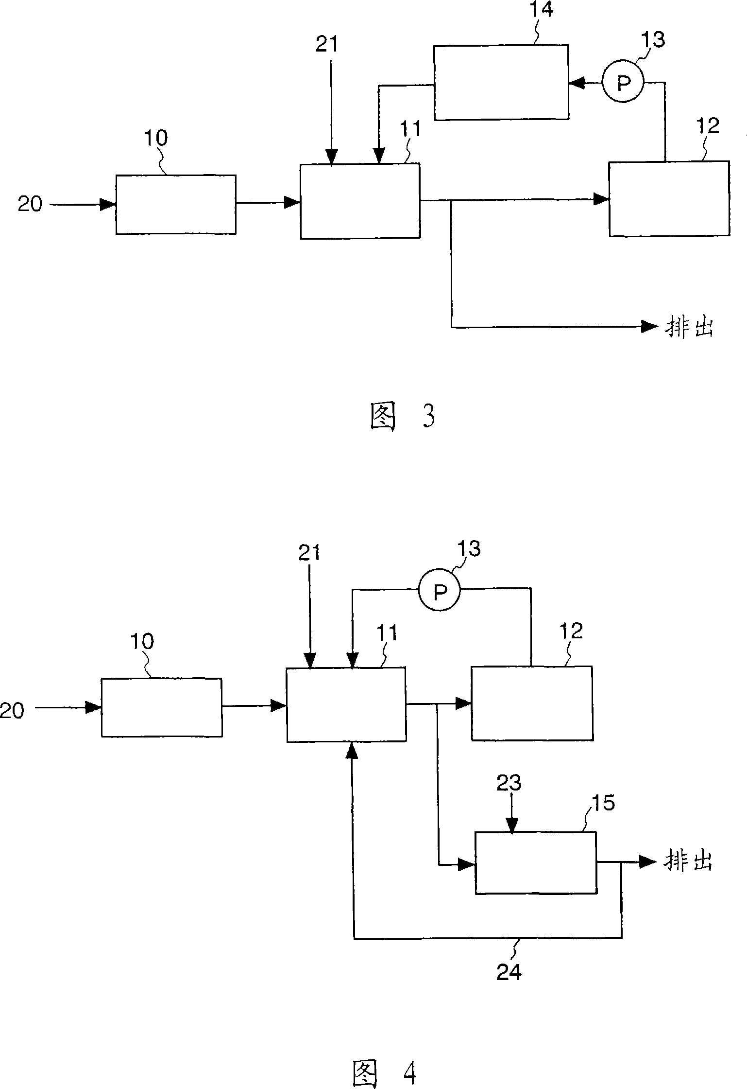
[0095] The structure of Example 3 shown in FIG. 3 is that, in addition to the structure of the above-mentioned Example 1, a denitrification device for denitrification by biological treatment is provided in the circulation system. It is provided with a biological treatment device 14 that introduces the electrolytic treatment solution from the above-mentioned electrolytic tank 12, and removes the NO remaining in the electrolytic treatment solution. 3 After -N, the treatment liquid flowing out from the biological treatment device 14 is introduced into the circulation adjustment tank 11 and circulated. In this embodiment, it is preferable that the electrolytic cell 12 is also of a sealed type.

[0096] The above-mentioned biological treatment device 14 is to make NO 3 -N decomposes to the device of nitrogen gas, can make proper use of biological fixed bed.

[0097] As described in this example, the NO in the electrolytic treatment solution is 3 -N removal device can reduce NO i...


PUM


Abstract

The object of the present invention is to provide an electrolytic treatment method and device for wastewater containing ammoniacal nitrogen, which can prevent the reduction of current efficiency and improve the decomposition efficiency of ammonia, and can safely and effectively treat all wastewater containing nitrogen . The electrolytic treatment device of the present invention is an electrolytic treatment device for wastewater containing ammoniacal nitrogen with the following parts: an adjustment tank (11) into which the wastewater containing ammoniacal nitrogen flows, and the electrolytic treatment is supplied by the adjustment tank under the condition of having chloride ions. The electrolytic cell (12) of the waste water (20), and the circulating pump (13) that makes the waste water circulate in the above-mentioned adjustment tank (11) and the above-mentioned electrolytic cell (12); wherein the above-mentioned electrolytic cell (12) has a pH value of 5 For electrolytic treatment of the above-mentioned waste water in the range above and less than 8, it is preferable to arrange a catalyst member formed of a metal material in the above-mentioned electrolytic cell (12) to promote the decomposition reaction of ammoniacal nitrogen.

Description

technical field [0001] The invention relates to an electrolytic treatment method and device for wastewater containing ammoniacal nitrogen, which electrolytically treats wastewater containing ammoniacal nitrogen under the condition of chloride ions, thereby decomposing ammoniacal nitrogen into nitrogen gas and removing it. Background technique [0002] Nitrogen contained in wastewater is one of the main factors rich in nutrients such as rivers, lakes, or inner bays, so it is necessary to remove nitrogen from wastewater. The nitrogen content contained in wastewater also varies according to the type and properties of the wastewater, but most of them exist in the form of ammoniacal nitrogen. At present, it has been proposed to efficiently decompose the ammoniacal nitrogen into harmless nitrogen. And remove the technology from wastewater, and put it into practical use. [0003] Typical methods for removing ammoniacal nitrogen in wastewater include biological denitrification trea...

Claims


Application Information

Patent Timeline
Patent Type & Authority Applications(China)
IPC IPC(8): C02F1/461
CPCC02F2101/16C02F2209/06C02F2301/046C02F1/4674
Inventor 水谷洋大村友章浅野昌道丰田一郎长克美池卓加藤雄大
Owner MITSUBISHI HEAVY IND ENVIRONMENTAL & CHEM ENG CO LTD
Learn More