Current sensor

A current sensor and current sampling technology, which is applied in voltage/current isolation, measuring current/voltage, instruments, etc., can solve the problems of relay protection device misoperation, secondary current distortion, and narrow frequency band, so as to achieve easy installation and Maintenance, wide dynamic range, not easy to burn out effect

Inactive Publication Date: 2008-07-23
SUZHOU SUDIAN SCI & TECH INST
View PDF0 Cites 5 Cited by
  • Summary
  • Abstract
  • Description
  • Claims
  • Application Information

AI Technical Summary

Problems solved by technology

[0004] 1. Large size, heavy weight and high price
[0005] 2. The current transformer has an iron core, and the output current is non-linear
[0006] 3. High-amplitude currents are prone to magnetic saturation, which seriously distorts the secondary current, causing malfunction and refusal of relay protection devices
[0007] 4. The measurement range is small, the frequency band used is narrow, and there are many varieties and specifications
[0008] 5. The measurement error is large, and the phase deviation is an inherent defect of the traditional transformer
[0009] 6. The cost of insulation is high, and the original air insulation, oil-paper insulation, gas insulation and cascaded insulation can no longer meet the requirements of ultra-high voltage insulation
[0010] 7. Electromagnetic resonance, flammable and explosive, etc.

Method used


Image

  • Current sensor

Examples


Embodiment

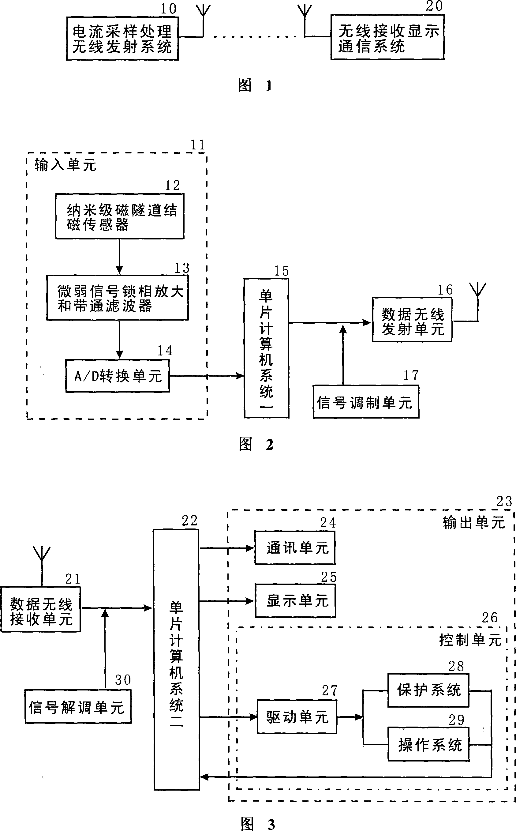
[0038] Embodiment: As shown in FIG. 1, a current sensor includes a current sampling and processing wireless transmitting system 10, and a wireless receiving and displaying communication system 20, and the current sampling and processing wireless transmitting system 10 and the wireless receiving and displaying communication system 20 pass through Connect wirelessly.

[0039] As shown in Figure 2, the current sampling processing wireless transmitting system 10 comprises an input unit 11, a single-chip computer system one 15, and a data wireless transmitting unit 16 connected in sequence; the input unit 11 comprises a nanoscale magnetic tunnel junction magnetic sensor 12 connected in sequence, Weak signal lock-in amplification and bandpass filter 13, A / D conversion unit 14. The A / D conversion unit 14 is connected to a single-chip computer system 15 . Also, a signal modulating unit 17 is connected to the data wireless transmitting unit 16 .

[0040] As shown in FIG. 3 , the wire...


PUM


Abstract

The invention discloses a current sensor, which comprises a current sampling wireless emission system (10) and a wireless receiving displaying communication system (20), wherein the systems (10, 20) are connected wirelessly, the system (10) comprises serially connected an input unit (11), a single-chip computer system (15) and a data wireless emitter (16), the input unit (11) uses a nanometer magnetic tunnel magnetic sensor (12) to sample signal. The invention has accurate measurement, high safety and reliability, wide application and strong adaptability, which is suitable for the application in high-voltage large-current condition. The invention has compact structure, low weight, low cost, easy installment and maintenance, which is suitable for network measurement and can meet the demands of modern electric power system as intelligentization, modularization, datamation, maintenance-free, miniaturization and multifunction.

Description

technical field [0001] The invention relates to a current sensor, in particular to a current sensor using nanoscale magnetic tunnel junction technology. Background technique [0002] Electromagnetic transformers have been fully developed for quite a long period of time, but some of their inherent weaknesses are difficult to meet the development needs of automation and digitalization of modern power systems. This has become the bottleneck of the rapid development of the power industry. [0003] The traditional electromagnetic transformer mainly has the following disadvantages: [0004] 1. Large size, heavy weight and high price. [0005] 2. The current transformer has an iron core, and the output current is non-linear. [0006] 3. High-amplitude currents are prone to magnetic saturation, which seriously distorts the secondary current, causing malfunction and refusal of relay protection devices. [0007] 4. The measurement range is small, the frequency band used is narrow,...

Claims


Application Information

Patent Timeline
Patent Type & Authority Applications(China)
IPC IPC(8): G01R19/00G01R33/02G01R15/20G08C17/00
Inventor 周金海罗超英陆海林蒋惠人
Owner SUZHOU SUDIAN SCI & TECH INST
Why Eureka
Try Eureka