Method and system for testing base station time delay

A technology for testing base stations and delays, applied in transmission systems, digital transmission systems, transmission monitoring, etc., can solve problems such as inability to accurately measure delays, lack of testing methods, and difficulties in delay analysis, and achieve rapid target locking and testing. The method is simple and the effect of narrowing the scope of the test

Active Publication Date: 2012-05-02
DATANG MOBILE COMM EQUIP CO LTD
View PDF0 Cites 0 Cited by
  • Summary
  • Abstract
  • Description
  • Claims
  • Application Information

AI Technical Summary

Problems solved by technology

However, this method can only test the delay of the entire network system. The delay inside a single network element cannot be accurately measured by the above method, which makes it difficult to analyze the delay of a single network element in the system.
At present, in the mobile communication system, less attention is paid to the testing of a single network element, especially the NodeB, and its testing methods are relatively scarce

Method used


Image

  • Method and system for testing base station time delay
  • Method and system for testing base station time delay
  • Method and system for testing base station time delay

Examples


Embodiment Construction

[0064] Embodiments of the present invention will be further described in detail below in conjunction with the accompanying drawings.

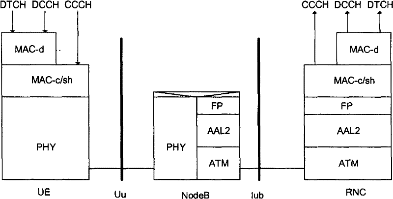
[0065] See figure 1 As shown in FIG. 2 , it is a schematic diagram of the connection relationship of each network element device in the communication system in the prior art. The base station (hereinafter collectively referred to as Node B) and the radio network controller (hereinafter collectively referred to as RNC) communicate through an Iub interface; between the described Node B and terminal equipment (hereinafter collectively referred to as UE) via a Uu air interface (hereinafter referred to as Uu air interface) ) connected. The main function of the Node B is to perform physical layer processing of the Uu air interface, such as channel interleaving and coding, rate matching and spreading. Such as figure 1 As shown, the physical layer (PHY, hereinafter referred to as PHY) of the NodeB demodulates after receiving the service data from th...


PUM


Abstract

The invention discloses a method for testing base station time delay which comprises: a sending step, service data is sent to a tested base station through a Uu air interface; a calculation step, the sum of an uplink physical interweaving and a processing time delay inside the base station and / or the sum of an uplink transmission time delay and a sending time delay of an Iub interface is evaluated according to a combination operation of the time that the service data respectively reaches an FP module of the base station, the time that the data is sent in the Uu air interface and the time thatthe data is sent in the Iub interface. At the same time, the invention also converts the service data into downlink data through the loop-back unit by mounting a loop-back line on an upstream sendingend of the Iub interface, and evaluates the sum of the uplink transmission time delay, the downlink transmission time delay and the sending time delay of the Iub interface by calculating the time difference that the service data is transmitted to the FP module through an uplink transmission and a downlink transmission. The embodiment of the invention can quickly and accurately test the time delayinside the base station and the time delay jitter.

Description

technical field [0001] The present invention relates to the field of wireless communication technology, in particular to a method for testing base station time delay applied to Time Division Synchronous Code Division Multiple Access (TD-SCDMA) and Wideband Synchronous Code Division Multiple Access (WCDMA) systems and system. Background technique [0002] A 3G network is usually divided into three parts: user equipment (UE), radio access network (UTRAN) and core network (CN). Wherein, the UTRAN is composed of one or more groups of radio network control subsystems (RNS, Radio Network Subsystems), each group of RNS includes a radio network controller (RNC, Radio Network Controller) and one or more base stations (Node B), the NodeB and the RNC communicate through the Iub interface, and the Node B and the UE communicate through the Uu air interface. [0003] In a mobile communication system, the delay and delay jitter of real-time services such as voice services in each device ...

Claims


Application Information

Patent Timeline
Patent Type & Authority Patents(China)
IPC IPC(8): H04B17/00H04W24/04H04L1/00H04W56/00
Inventor 李国荣丁立曼李青
Owner DATANG MOBILE COMM EQUIP CO LTD
Why Eureka
Try Eureka