On-site comprehensive approach for wastewater, artesian well, waste slurry and engine waste gas

An engine, waste mud technology, applied in dewatering/drying/concentrating sludge treatment, chemical instruments and methods, heating water/sewage treatment, etc., can solve the problems of hidden environmental hazards and high cost

Inactive Publication Date: 2008-08-20
广汉欣欣实业有限公司 +1
View PDF5 Cites 8 Cited by
  • Summary
  • Abstract
  • Description
  • Claims
  • Application Information

AI Technical Summary

Problems solved by technology

The main problems are: limited by factors such as chemical purification costs, energy consumption, operation and management of process equipment, and environmental capacity around the well site, the above-mentioned method of separately treating wastewater, waste mud and engine exhaust gas is costly and leaves environmental hazards

Method used


Image

  • On-site comprehensive approach for wastewater, artesian well, waste slurry and engine waste gas

Examples


Embodiment 1

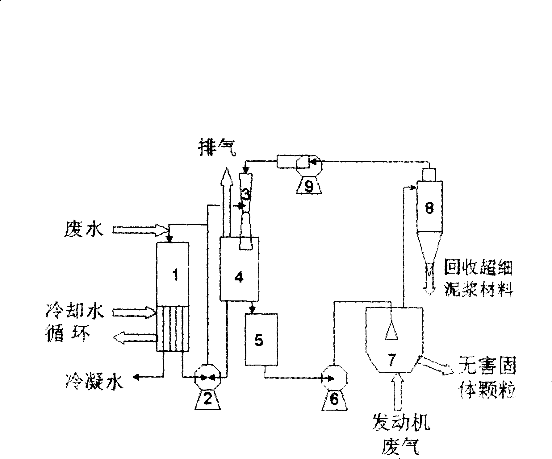
[0009] Example 1: 500kW diesel engine circulating cooling water treatment waste water 900kg / h and reclaim 855kg / h condensed water, engine exhaust treatment 260kg / h of waste mud with a solid rate of 33% and recycle 80kg / h ultrafine powder mud material Circulating water at 95-105°C convects and releases heat between the tubes of the first-effect falling-film heating section in the three-effect falling-film evaporator 1, so that the waste water pushed down by the fluid column in the second-effect falling-film heating section is heated in the tube to T eva1 =75~95℃ and film evaporation under the pressure drop of 38~84kPa, the evaporation intensity is 14~20kg / (h·m 2 ), the evaporation load is 220-315kg / h; the generated first-effect steam condenses and releases heat between the tubes of the second-effect falling-film heating section of device 1, so that the waste water pushed down by the liquid column in the third-effect falling-film heating section is heated in the tube warm up to...

Embodiment 2

[0011] Example 2: 500kW diesel engine circulating cooling water treats 900kg / h of waste water and recycles 855kg / h of condensed water, and treats 260kg / h of waste mud with a solid content of 33% in engine exhaust to make it thermally decompose at high temperature to achieve harmless 95~ The circulating water at 105°C convects and releases heat between the tubes of the first-effect falling-film heating section in the three-effect falling-film evaporator 1, so that the wastewater pushed down by the fluid column in the second-effect falling-film heating section is heated in the tube to T eva1 =75~95℃ and film evaporation under the pressure drop of 38~84kPa, the evaporation intensity is 14~20kg / (h·m 2 ), the evaporation load is 220-315kg / h; the generated first-effect steam condenses and releases heat between the tubes of the second-effect falling-film heating section of device 1, so that the waste water pushed down by the liquid column in the third-effect falling-film heating secti...


PUM

PropertyMeasurementUnit
strengthaaaaaaaaaa

Abstract

The invention relates to an on-site comprehensive treatment method for wastewater, waste mud during drilling wells and the engine exhaust, which comprises the following methods: using waste to control waste by utilizing the residual heat of circulating cooling water to treat wastewater through the multi-effect evaporation, treating the waste mud by fluidization drying through the engine exhaust residual heat and high temperature thermal decomposition, and removing the exhaust gas and harmful substances and reducing the exhaust noise. Take a diesel engine with the power of 500 KW for example, the diesel engine is able to simultaneously treat the wastewater at the speed of 900 kg/h and recover 90-95 % of the wastewater in the form of condensed water, treat the water mud with a solid content rate of 10-40 % at a speed of 260kg/h and disperse the waste mud into fog drops, which are in counter current contact with the engine exhaust gas of 200-380 DEG C and conduct heat and mass transfer with exhaust gas, and finally are heated in a fluidized bed to be recovered in harmless solid phase particles or in superfine powder; meanwhile, the engine exhaust gas conducts momentum, heat and mass transfers with the particles in the fluidized bed as well as the fog drops above the fluidized bed, so as to cool and abate the noise, then the waste water is used to wash away the harmful substances; all the consumption of external power does not exceed 30 kW.

Description

technical field [0001] The invention relates to an on-site comprehensive treatment method for waste water, drilling waste mud and engine exhaust gas, using engine waste heat as a heat source and engine exhaust gas as a carrier gas, purifying waste water through evaporation and condensation, recovering the active components of waste mud through fluidized drying, and recovering the active components of waste mud through high temperature Fluidized decomposition makes waste mud slag harmless, engine exhaust gas is purified at the same time, and exhaust noise is reduced. Background technique [0002] The treatment of waste water, drilling waste mud and engine exhaust gas is an environmental protection problem that must be solved at the drilling site. In the prior art, waste water is mainly treated by chemical purification and discharged up to the standard; waste mud is treated by solidification landfill or incineration; and engine exhaust gas is mainly treated by adding a muffler...

Claims


Application Information

Patent Timeline
Patent Type & Authority Applications(China)
IPC IPC(8): C02F1/04C02F11/12B01D53/14
Inventor 夏小全朱家骅夏素兰周勇
Owner 广汉欣欣实业有限公司
Why Eureka
Try Eureka