Encapsulation structure and high heat conducting reflexion cap of diode point matrix / nixie tube

A reflective cover, high thermal conductivity technology, applied in the direction of identification devices, instruments, etc., can solve the problems of printed circuit wiring difficulties, increase energy consumption, large printed circuit board space, etc., to reduce the pixel pitch of the display, prolong the service life, The effect of smooth cooling channels

Inactive Publication Date: 2008-08-27
CONCORD OPTO ELECTRIC TECH QUANZHOU
View PDF0 Cites 12 Cited by
  • Summary
  • Abstract
  • Description
  • Claims
  • Application Information

AI Technical Summary

Problems solved by technology

The disadvantages of the packaging structure of the existing dot-matrix display screens are that the LED chip 2 is installed on the printed circuit board 3, which takes up a large amount of space on the printed circuit board, and the wiring of the printed circuit is difficult, resulting in a large display pixel pitch. If the dot pitch is more than 10mm, it is difficult to achieve the dot pitch of the indoor display screen below 3mm, resulting in poor display resolution, large viewing angle of the outdoor display screen, and unsatisfactory practicability; in addition, the LED chip is fixed on a

Method used


Image

  • Encapsulation structure and high heat conducting reflexion cap of diode point matrix / nixie tube
  • Encapsulation structure and high heat conducting reflexion cap of diode point matrix / nixie tube
  • Encapsulation structure and high heat conducting reflexion cap of diode point matrix / nixie tube

Examples


Embodiment 1

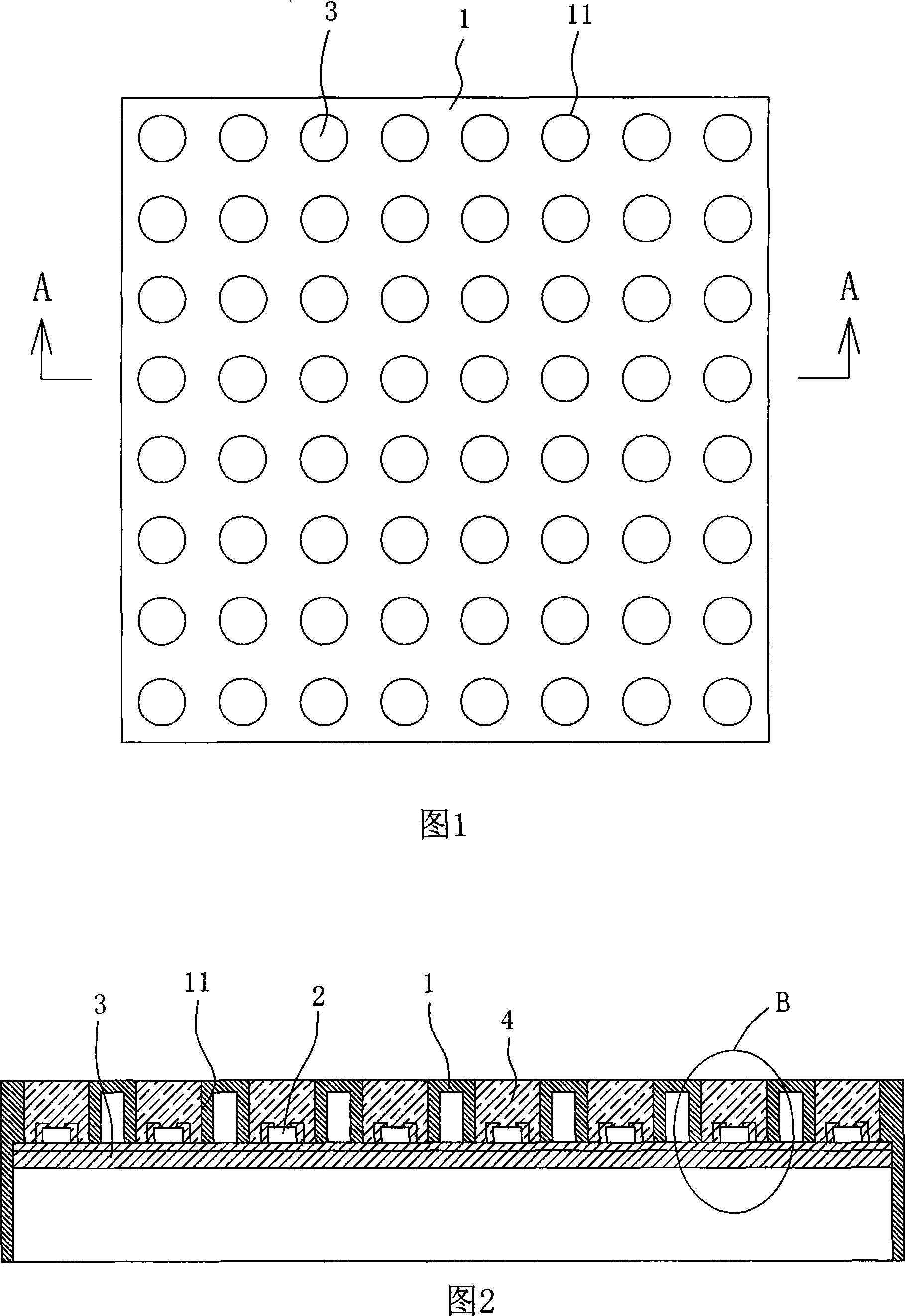
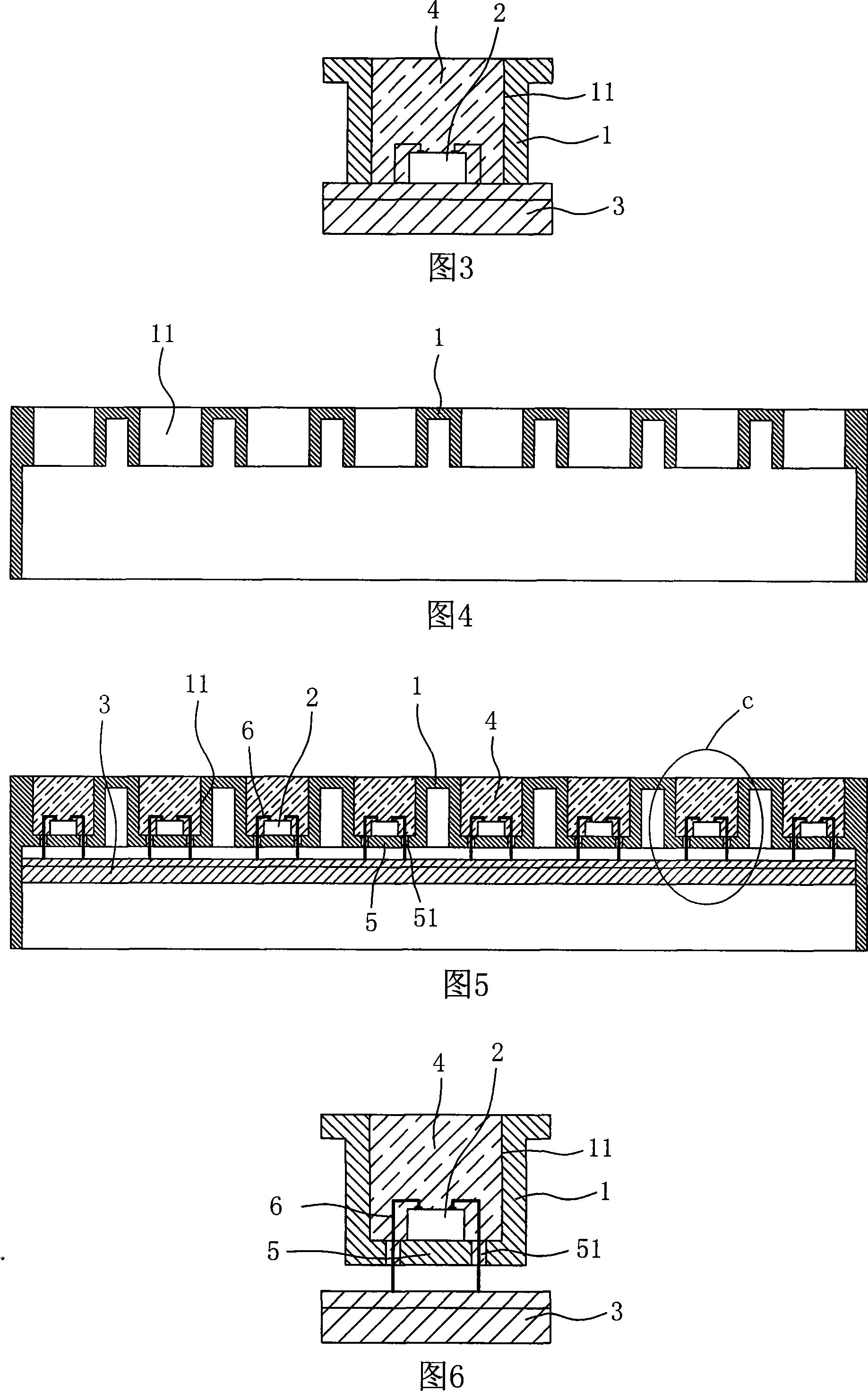
[0023] Embodiment 1: Refer to Fig. 5 to Fig. 7 . The packaging structure of the light-emitting diode dot matrix / digital tube mainly includes a reflective cover 1, an LED chip 2, a printed circuit board 3, and a transparent package for packaging the LED chip.

[0024] Refer to Figures 5 to 7. The reflective cover is made of high thermal conductivity materials such as aluminum, copper, aluminum-copper alloy or high thermal conductive ceramics; the reflective cover 1 is provided with pixel holes 11 arranged in a dot matrix in multiple rows. The bottom of each pixel hole 11 of the reflective cover 1 is provided with a bridging bottom 5 integrally formed with the reflective cover for fixing and installing the LED chip 2; the bridging bottom 5 is a circular plate matching the bottom surface of the pixel hole, and the circular plate Line passing holes 51 are correspondingly provided on both sides of the middle part. The circuit board 3 is fixedly embedded in the inner cavity of the...

Embodiment 2

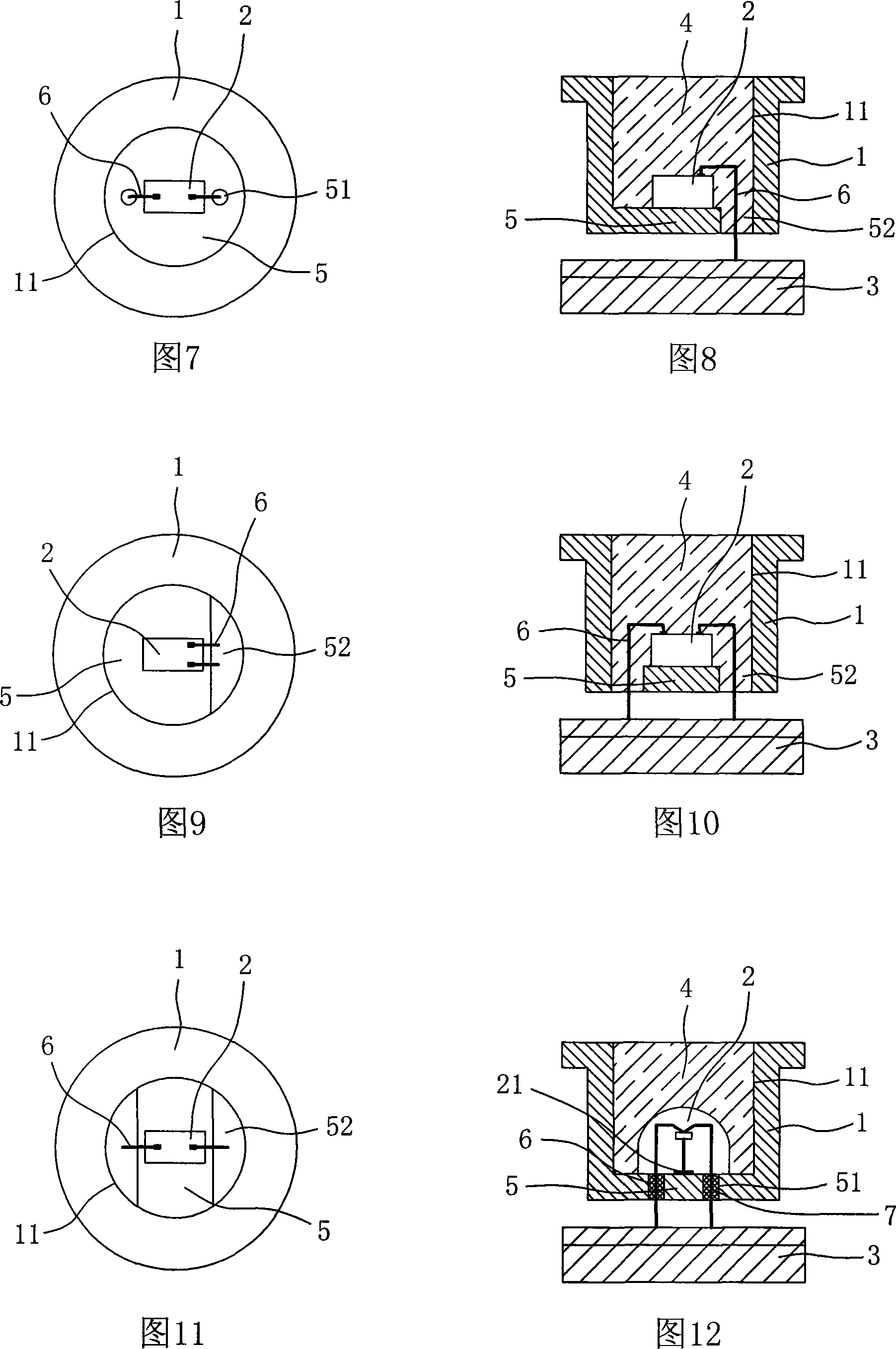
[0026] Embodiment 2: Refer to Fig. 8 and Fig. 9 . The difference between this embodiment and embodiment 1 is:

[0027] The bridging bottom 5 at the bottom of each pixel hole 11 of the reflective cover 1 is a D-shaped plate matching the bottom surface of the pixel hole. There is a gap 52 between one side of the D-shaped plate and the inner wall of the pixel hole 11, and the gap 52 forms a line. space. The LED chip 2 is inverted and fixed on the top surface of the bridging bottom 5 by gluing or eutectic welding. The two terminals on the front of the LED chip 2 are connected to the circuit board 3 through the gold wire 6 respectively. One end is electrically connected to the corresponding terminal on the front of the LED chip 2 , and the other end is electrically connected to the corresponding electrode of the circuit board 3 through the gap 52 . The rest of the structure is the same as that of Embodiment 1, and will not be repeated here.

Embodiment 3

[0028] Embodiment 3: Refer to Fig. 10 and Fig. 11 . The difference between this embodiment and embodiment 1 is:

[0029] The bridging bottom 5 at the bottom of each pixel hole 11 of the reflector cover 1 is an inline strip that is bridged between the middle parts of both sides of the inner peripheral wall of the pixel hole, and there is a gap 52 between the two sides and the inner wall of the pixel hole. The void 52 forms the wire passing space. The LED chip 2 is fixed upside down on the top surface of the bridging bottom 5 by gluing or eutectic welding. The two terminals on the front of the LED chip 2 are connected to the circuit board 3 through the gold wire 6 respectively. One end is electrically connected to the corresponding terminal on the front of the LED chip 2 , and the other end is electrically connected to the corresponding electrode of the circuit board 3 through the gap 52 . The rest of the structure is the same as that of Embodiment 1, and will not be repeated ...


PUM


Abstract

The invention relates to a diode point matrix/nixietube high thermal conduction reflecting cover and a packaging structure thereof; the reflecting cover is made of high thermal conduction material; the pixel hole bottom of the reflecting cover is provided with a bridge connection base which is integrated with the reflecting cover and used for fixedly mounting an LED chip; the bridge connection base is provided with wire-passing space for the wire tapping and passing-through of the LED chip; the LED chip is fixed on the top surface of the bridge connection base; the connected and tapped wires of two electrode terminals of the LED chip respectively pass through the wire-passing space and are electrically conducted with a circuit board; a transparent packaging body is affused in the pixel hole. The LED chip is directly arranged on the bridge connection base; heat energy generated by the chip is directly emitted and removed through the reflecting cover; the use current of the LED can be increased to improve the brightness of a display screen and ensure the high definition of the display screen; the mass effective space of the circuit board is released to ensure wiring space of the circuit board; a display pixel point pitch is reduced in order that the display screen has perfect high-definition and high-resolution, thereby solving the technical problem of a large visual angle of an outdoor display screen.

Description

technical field [0001] The invention relates to the technical field of light emitting diode dot matrix / digital tube display screens, in particular to a high thermal conductivity reflective cover of light emitting diode dot matrix / digital tube and a package structure of LED chips thereof. Background technique [0002] Figures 1 to 3 show the LED packaging structure of existing full-color, two-color or single-color dot matrix / digital tubes: mainly including plastic reflective cover 1, LED chip 2 and printed circuit board 3; reflective cover 1 Dot matrix pixel holes 11 (see Figure 4 for details) are arranged on the top, and the LED chips 2 are fixed on the printed circuit board 3 to form a pixel unit module; A transparent encapsulation body 4 made of epoxy resin, silica gel or other transparent materials to encapsulate the LED chip 2 . The disadvantages of the packaging structure of the existing dot-matrix display screens are that the LED chip 2 is installed on the printed cir...

Claims


Application Information

Patent Timeline
IPC IPC(8): G09F9/33
Inventor 林明德曾有助林威谕
Owner CONCORD OPTO ELECTRIC TECH QUANZHOU
Why Eureka
Try Eureka