Score slot coil unit for low-speed high torque permanent magnetic brushless electromotor

A permanent magnet brushless motor, fractional slot technology, applied in the field of fractional slot winding, can solve the problems of low speed and large torque limitation, not too much, large number of slots, etc., to reduce the amount of iron used, the production process is simple, and the processing cost effect

Active Publication Date: 2010-06-23
BEIJING ZHONG KE SAN HUAN HI TECH
View PDF3 Cites 1 Cited by
  • Summary
  • Abstract
  • Description
  • Claims
  • Application Information

AI Technical Summary

Problems solved by technology

However, as the number of magnetic poles and phases increases, the number of motor slots of a certain size will increase several times. Due to the limitation of mechanical technology, the number of magnetic poles and phases cannot be too much. Therefore, the characteristics of low-speed high-torque are limited to a certain extent.
Due to the complexity of the process of traditional fractional slot windings, and the number of slots is far greater than the number of magnetic poles, fractional slot windings are mostly used in large hydroelectric generators and AC motors for special purposes, and most motors do not use them.

Method used


Image

  • Score slot coil unit for low-speed high torque permanent magnetic brushless electromotor
  • Score slot coil unit for low-speed high torque permanent magnetic brushless electromotor
  • Score slot coil unit for low-speed high torque permanent magnetic brushless electromotor

Examples


Embodiment 1

[0041] Fractional slot windings for in-wheel motors for electric vehicles

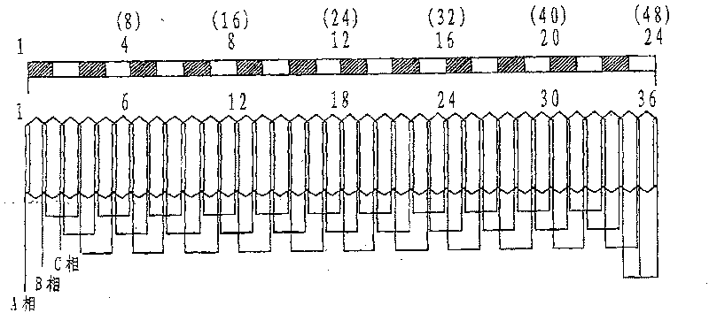
[0042] Figure 5 It is a schematic diagram of the local structure of the electric vehicle hub motor, in which the fractional slot winding form and connection refer to image 3 As shown in Table 2, the coils of this winding are embedded in the slots of the stator core, corresponding to the magnetic poles arranged alternately on the N and S poles on the rotor. Three (that is, distribution number Q=3) series windings are distributed in the phase band to form a phase winding, and the other phase windings are arranged circularly in sequence according to the phase sequence of the motor.

[0043] The number of magnetic poles P, the number of iron core slots Z, the number of phases M, and the number of distributions Q in this embodiment satisfy the condition 1) when the number of distributions Q is an odd number, the number of iron core slots Z=Q×M×K, and the number of magnetic poles P= Z±K; where Q=1, 3, 5,...

Embodiment 2

[0046] Fractional slot windings for wind turbines

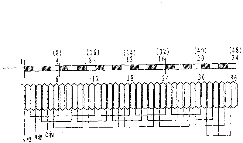
[0047] Figure 6 It is a schematic diagram of the local structure of the permanent magnet wind turbine, and the fractional slot winding form and connection refer to Figure 4 And Table 5, the coil of this winding is embedded in the slot of the stator core, corresponding to the magnetic poles arranged alternately on the N and S poles on the rotor, the winding pitch of the winding is 1 slot pitch, double-layer stacked winding, in a Four windings in series (that is, the distribution number Q=4) are distributed in the phase band to form a phase winding, and the other phase windings are arranged circularly in sequence according to the phase sequence of the motor.

[0048] The number of magnetic poles P, the number of iron core slots Z, the number of phases M, and the number of distributions Q in this embodiment satisfy the condition 2) when the number of distributions Q is an even number, the number of iron core slots Z=Q×M×K, an...

Embodiment 3

[0052] Small power permanent magnet slotless end face (plane) rotor brushless motor

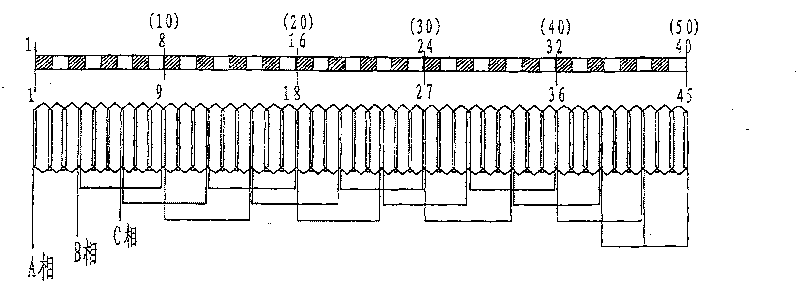
[0053] Figure 7 Small power permanent magnet slotless end face (plane) rotor brushless motor winding surface schematic diagram, fractional slot winding form and connection reference image 3 And Table 2, the inner stator core 3 is made of magnetically permeable material (disc type), and the motor winding is glued on the end surface without slots, and 36 equal parts are evenly distributed on the end surface of the disc, that is, 36 virtual slots 4, each equal Parts have double-layer distributed windings. The permanent magnetic pole 2 adopts NdFeB fan-shaped magnetic steel, and the N and S magnetic poles are alternately and evenly distributed. The power of the motor is 500W, the slotless planar structure, the number of virtual slots Z = 36, the number of poles P = 32, three-phase low-speed and large-torque DC brushless motor.


PUM


Abstract

The invention relates to a fractional slot winding of a permanent magnet brushless motor, which comprises a stator core of unslotted structure. The coils of the winding are arranged on the end of the stator core and corresponding to magnetic poles which are in alternate arrangement with an N pole and an S pole on a rotor; the pitch of the winding is 1 slot pitch and the winding is in double lap wound. The winding of the invention is characterized in that: number of magnetic poles P, number of core slots Z, phase number M and distribution number Q meet the following conditions: 1) when the distribution number Q is odd, the number of core slots Z equales that Q is multiplied by M and then multiplied by K, number of magnetic poles P equals that Z plus or minus K; wherein, K is a natural number; 2) when the distribution number Q is even, number of core slots Z equals that Q is multiplied by M and then multiplied by K, number of magnetic poles P equals that Z plus or minus 2K; wherein, K is a natural number. The fractional slot winding is applicable to low speed high torque permanent magnet brushless motors of various sizes and power grades and since the pitch of the winding is 1 slot pitch, the end length of the motor winding is obviously shortened, thus winding materials and energy are saved; meanwhile, the winding of the invention has simple production technique, is suitable formass industrial manufacture and can reduce processing cost of a permanent magnet.

Description

technical field [0001] The invention belongs to the technical field of permanent magnet brushless motors, in particular, the invention relates to fractional slot windings in which the multiphase multipole winding pitch is one slot pitch in the permanent magnet brushless motor. Background technique [0002] Brushless motor is a new type of DC motor developed with the rapid development of electronic technology in the 1950s. Its excellent characteristics are also revealed in the direct drive system. The winding of the brushless motor usually adopts a three-phase star winding, the minimum number of magnetic poles is 2 poles, and the corresponding number of slots is at least 6 slots, if it is 4 poles, it is 12 slots, etc., that is, the number of slots is usually 3 of the magnetic poles. (number of phases) times (Ye Jinhu et al: "Brushless DC Motor", Science Press (First Edition) 1982.1, pp 17-20); in low-speed brushless motor systems, most of them adopt multi-pole structure or m...

Claims


Application Information

Patent Timeline
Patent Type & Authority Patents(China)
IPC IPC(8): H02K3/12H02K1/27H02K1/16
Inventor 王玉国贾敬东
Owner BEIJING ZHONG KE SAN HUAN HI TECH
Why Eureka
Try Eureka