

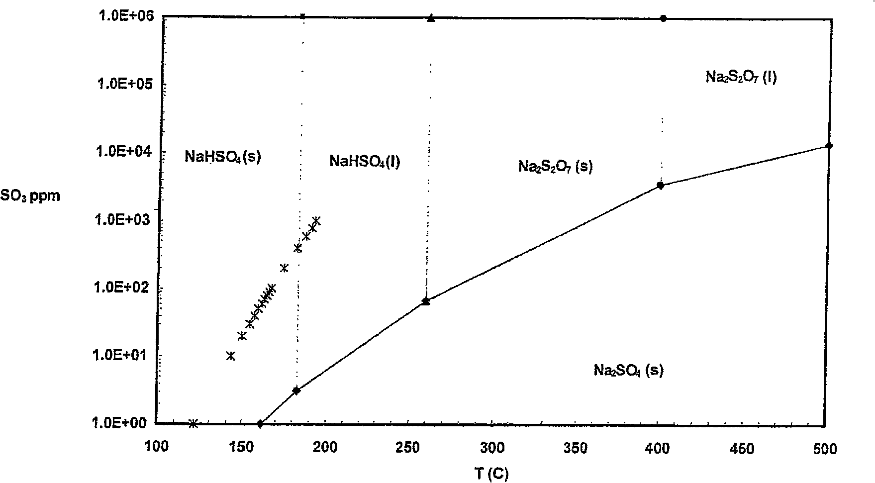
Sulfur trioxide removal from a flue gas stream
A flue gas and flue technology, applied in chemical instruments and methods, separation of dispersed particles, separation methods, etc., can solve the problems of frequent cleaning of process equipment, low efficiency, adhesion, etc.
- Summary
- Abstract
- Description
- Claims
- Application Information
AI Technical Summary
Problems solved by technology
Method used
Image

Examples
Embodiment Construction
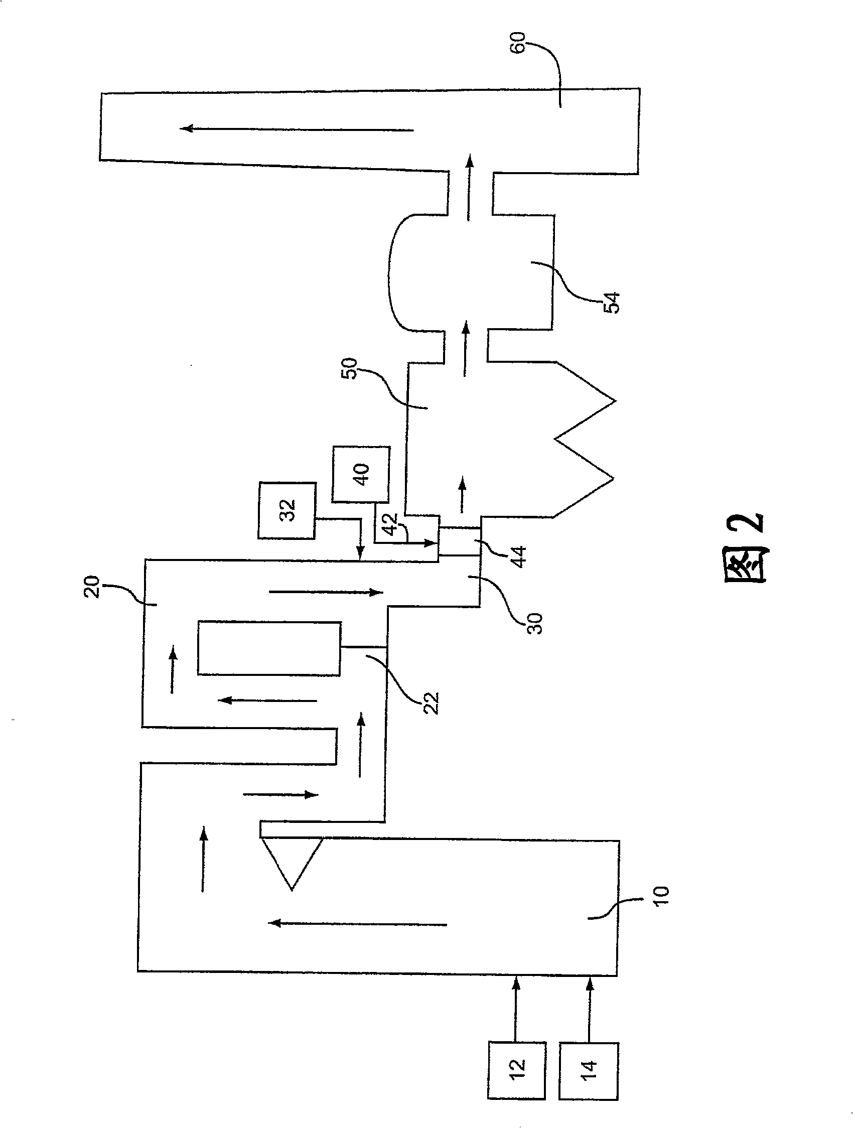
[0039] A hot-side electrostatic precipitator (ESP) is employed in the power plant and no baghouse is used. The device removes NO using x catalyst, causing SO in the flue gas 3 level up. SO in flue gas 3 The concentration is from about 100 ppm to about 125 ppm. Jet from Solvay Chemicals Trona to remove SO from flue gas 3 .
[0040] As a comparative example, no additives were used, and trona was sprayed at 400°F with an NSR of about 1.5. The ESP perforated plates in this unit showed significant solids buildup and required frequent cleaning.
[0041] An absorbent composition comprising trona and 1% calcium carbonate was sprayed into the flue gas at 400°F with an NSR of about 1.5. in operation SO 3 The ESP perforated plates in this unit were relatively free of solids buildup after removal from the system.
[0042] The use of additives according to the present invention reduces the SO 3 The amount of sticky waste that is removed from the process.
[0043] The embodimen...
PUM
| Property | Measurement | Unit |
|---|---|---|
| The average particle size | aaaaa | aaaaa |
| The average particle size | aaaaa | aaaaa |
| The average particle size | aaaaa | aaaaa |
Abstract
Description
Claims
Application Information