
Twin-triode current control type self-oscillation flyback converter

A flyback converter, current control technology, applied in the direction of converting DC power input to DC power output, adjusting electrical variables, and controlling/regulating systems, etc. problems, to achieve the effect of shortening the turn-off time, fast dynamic response, and improving the efficiency of the whole machine

Inactive Publication Date: 2008-09-24
MORNSUN GUANGZHOU SCI & TECH
View PDF0 Cites 17 Cited by
  • Summary
  • Abstract
  • Description
  • Claims
  • Application Information

AI Technical Summary

Problems solved by technology

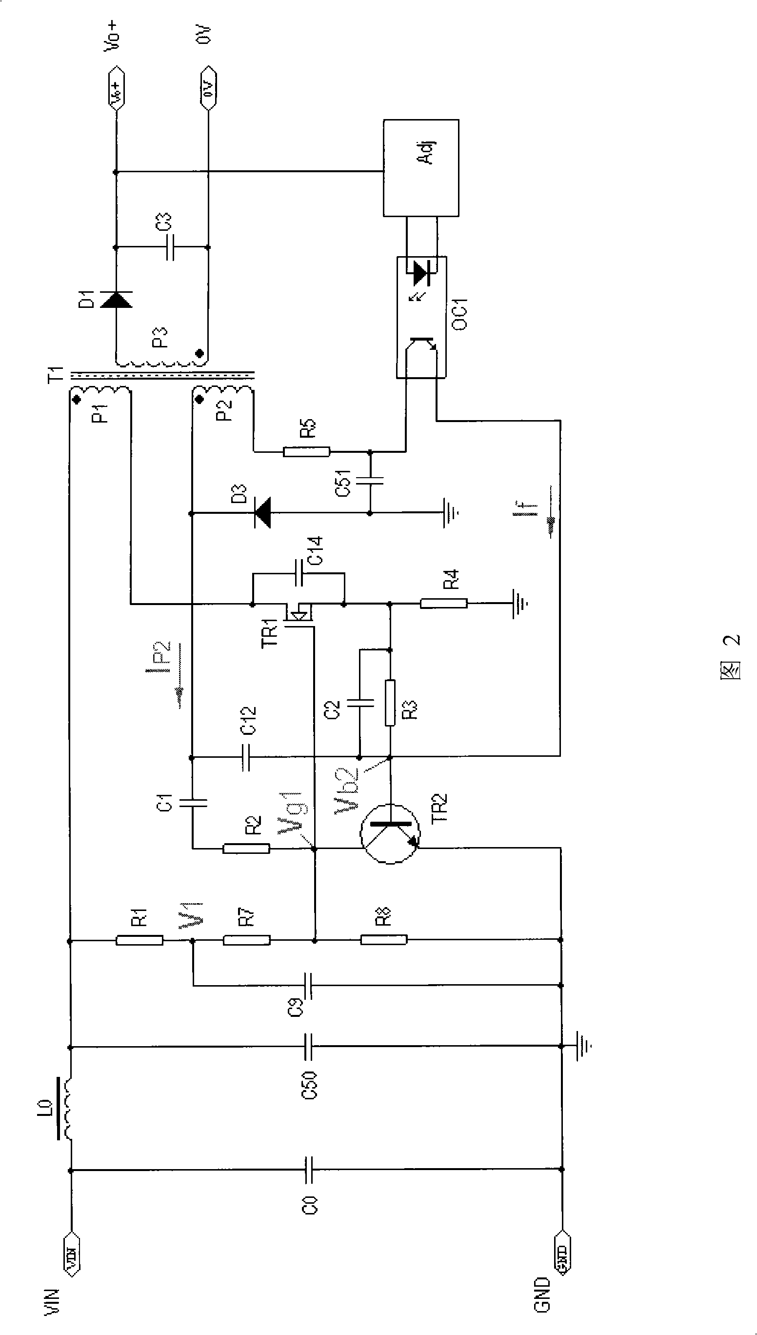
Assuming a product with a nominal input voltage of 5VDC and an output power of 3W, the input voltage varies between 4.5 and 9VDC, when a short circuit occurs, the input voltage is 5VDC, and the short circuit current is 0.34A, then the short circuit power Ps=5*0.34=1.7 W; if the input voltage is 9VDC and the short-circuit current is 0.27A, then the short-circuit power Ps=9*0.27=2.43W, it can be seen that the short-circuit power consumption increases
On the other hand, when the potential of the Vg1 point is higher than the potential of the V1 point, the current will flow in the opposite direction to the previous stage, causing interference to the previous stage circuit
At the same time, due to the discrete nature of the transformer winding process, the primary and secondary windings are uneven, resulting in large primary and secondary leakage inductance, and a sharp increase in short-circuit power consumption.
[0008] In the case where the input voltage of the above circuit changes greatly, especially in the micro-power circuit with the power below 10W, the input voltage change ratio is in the range of 2:1 to 4:1 or more, and some difficult problems have appeared in practical applications. The main disadvantages are as follows: waveform distortion occurs when the MOS tube TR1 is cut off, which increases the switching loss of the MOS tube TR1, making the overall efficiency of the product not high; increases the product noise; the short-circuit power is large, and increases with the increase of the input voltage; the MOS tube The drain-source voltage Vds peak voltage difference of TR1 is high; the operating frequency changes with the input voltage and output load, and EMI electromagnetic compatibility is difficult to design; it is easy to generate oscillation during no-load operation, resulting in unstable output voltage

Method used


Image

  • Twin-triode current control type self-oscillation flyback converter
  • Twin-triode current control type self-oscillation flyback converter
  • Twin-triode current control type self-oscillation flyback converter

Examples


Embodiment Construction

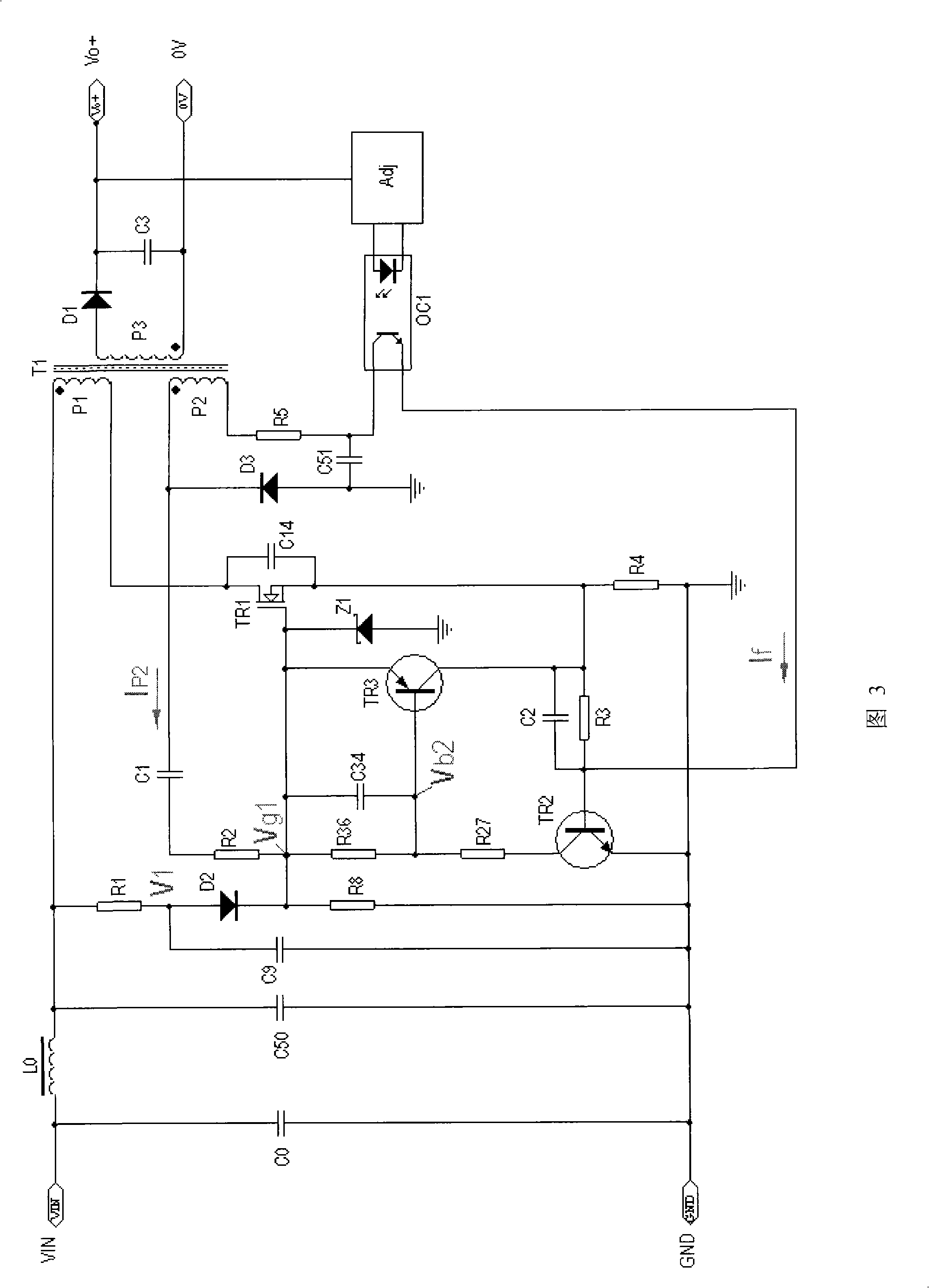
[0032] As shown in Figure 3, it mainly includes the soft start part, MOS transistor TR1, transformer T1, pulse frequency modulation part (PFM), reference amplifier part, optocoupler isolation, voltage regulator output circuit part.

[0033] The pulse frequency modulation part mainly includes NPN transistor TR2, PNP transistor TR3, capacitors C1, C2, resistors R2, R3, R4, R27, R36, C34, regulator Z1, freewheeling diode D3 and feedback winding P2, etc. . One way of the input voltage is connected to the gate of MOS transistor TR1 through the soft start part, and the other is connected to the same-named end of the primary winding P1. R4 is grounded and connected to the base of the triode TR2 through the bias resistor R3, the capacitor C2 is connected in parallel at both ends of the resistor R3, the collector of the triode TR2 is connected to the resistor R27, and the emitter of the triode TR2 is grounded; the end of the feedback winding P2 with the same name is connected to the MO...


PUM


Abstract

The invention discloses a double triode current control self oscillation flyback converter which comprises a soft start part, a MOS tube TR1, a transformer T1, a pulse frequency modulating part, a benchmark amplifying part, an insulating optical coupler OC1 and a voltage regulation output loop part; an input electric quantity is connected with the output loop part by the transformer T1; wherein, the pulse frequency modulating part mainly comprises a triode TR2, a resistance R2, a capacitance C2 and a resistance R4; the base electrode of the triode TR2 is connected with the source electrode of the MOS tube TR1 by an bias resistance R3 and a capacitance C2 which are connected in parallel; the source electrode of the MOS tube TR1 is grounded by the resistance R4; the pulse frequency modulating part is additionally provided with an triode current control circuit; the triode current control circuit is connected between the MOS tube TR1 and the triode TR2 to realize the self oscillation output of the double triode current control at the input end. The converter of the invention has the advantages of high working efficiency and working with no load, which can ensure the output voltage to be stable, the powers for no load work and short circuit to be very low and realizes continuous short circuit protection and fast dynamic response.

Description

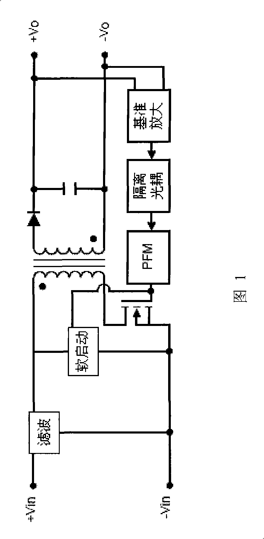
technical field [0001] The invention relates to a self-oscillating flyback converter applied to a low-power DC-DC conversion power supply, in particular to a self-oscillating flyback converter with dual triode current control at the input end. Background technique [0002] The ideal circuit schematic diagram of self-oscillating flyback converter (RCC) in the prior art is shown in Figure 1, which mainly includes filtering part, soft start part, MOS tube, transformer, pulse frequency modulation part (PFM), reference amplifier Part, isolated optocoupler, voltage regulator output circuit part. The input power is connected to the output circuit part through the transformer, the soft start part is connected to the gate of the MOS tube, and the gate of the MOS tube is also connected to the pulse frequency modulation part. , forming a voltage negative feedback loop. [0003] A self-oscillating flyback converter for a low-power DC-DC conversion power supply commonly used in the ind...

Claims


Application Information

Patent Timeline
Patent Type & Authority Applications(China)
IPC IPC(8): H02M3/335G05F1/10
CPCH02M3/3385
Inventor 尹向阳
Owner MORNSUN GUANGZHOU SCI & TECH
Learn More