Millimeter wave band broadband cylinder conformal 4*4 microstrip antenna as well as design method thereof

A millimeter-wave band and microstrip antenna technology, which is applied in antennas, antenna arrays, antenna supports/mounting devices, etc., can solve the problems of high integration of millimeter-wave circuits, difficulties in accurate analysis of antenna performance, and serious coupling between antennas and circuits. , to achieve the effect of improving bandwidth and coupling efficiency, good polarization purity, and simple design method

Inactive Publication Date: 2008-10-08
HARBIN INST OF TECH
View PDF0 Cites 25 Cited by
  • Summary
  • Abstract
  • Description
  • Claims
  • Application Information

AI Technical Summary

Problems solved by technology

Due to the following difficulties in the design of conformal antennas in the millimeter-wave band: the millimeter-wave circuit has a high degree of integration, the coupling between the antenna and the circuit is serious, and the design is difficult; the complex structure of the conformal antenna makes accurate analysis of the antenna performance very difficult, and requires the structure Fine, high precision requirements, complex processing technology, so there is no mature and perfect cylindrical conformal antenna publicly available in China

Method used


Image

  • Millimeter wave band broadband cylinder conformal 4*4 microstrip antenna as well as design method thereof
  • Millimeter wave band broadband cylinder conformal 4*4 microstrip antenna as well as design method thereof
  • Millimeter wave band broadband cylinder conformal 4*4 microstrip antenna as well as design method thereof

Examples


specific Embodiment approach 1

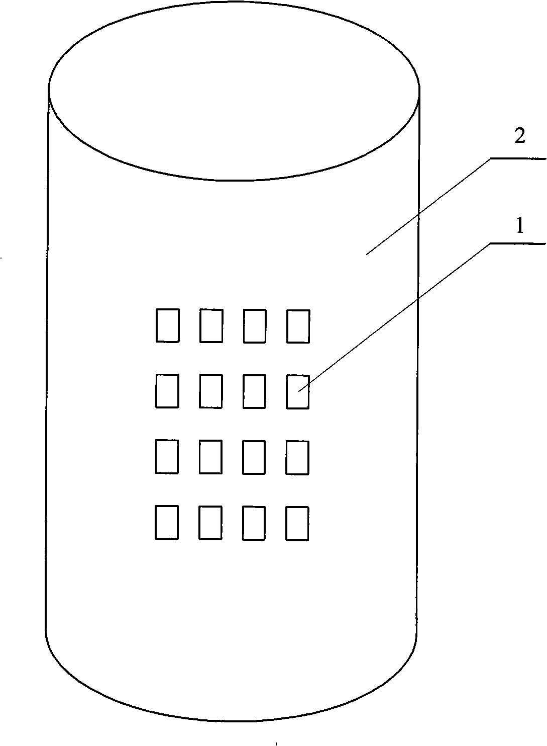
[0010] Specific implementation mode one: combine figure 1 ~ Figure 3 and Figure 8 ~ Figure 10 Describe this embodiment, the microstrip antenna of this embodiment is made up of sixteen antenna units 1 and cylindrical carrier 2; Said sixteen antenna units 1 are divided into four groups, and each group of four antenna units 1 is arranged in a rectangular shape, four The group antenna unit 1 is arranged on the surface of the cylindrical carrier 2 in a rectangular shape as a whole, and the antenna unit 1 is composed of a first dielectric layer 3, a second dielectric layer 4, an intermediate floor 10, a patch layer 5, and a feed network layer 6 , the inner surface of the feed network layer 6 is affixed to the surface of the cylindrical carrier 2, the outer surface of the feed network layer 6 is affixed to the inner surface of the first dielectric layer 3, and the outer surface of the first dielectric layer 3 is affixed to the inner surface of the first dielectric layer 3. The inne...

specific Embodiment approach 2

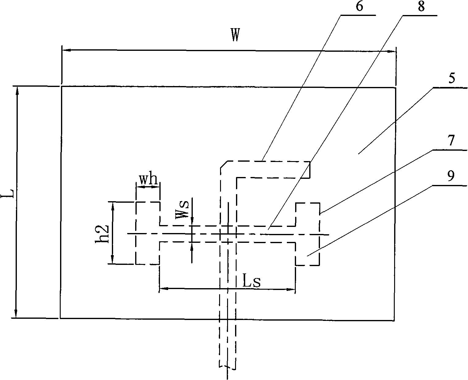
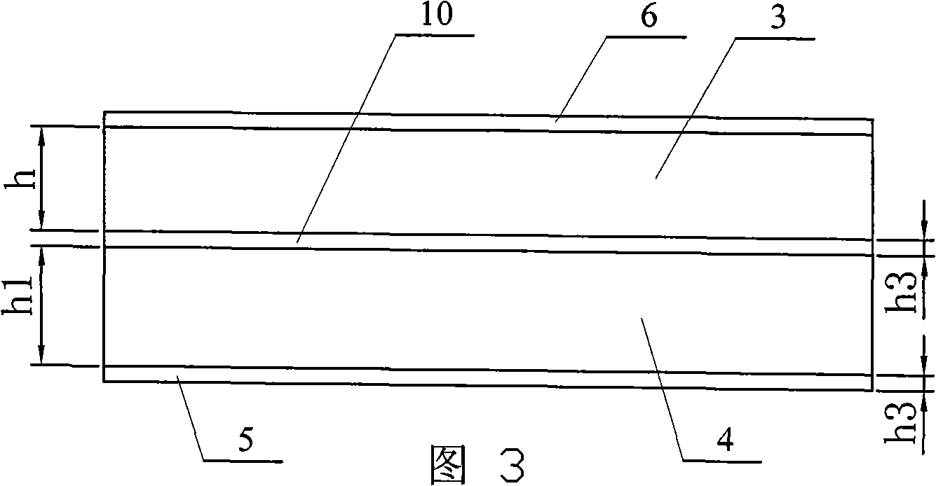
[0011] Specific implementation mode two: combination figure 1 and Fig. 3 illustrate the present embodiment, the thickness h of the first dielectric layer 3 of the present embodiment is 0.25mm, the thickness h1 of the second dielectric layer 4 is 0.50mm, the thickness h3 of the middle floor 10 and the patch layer 5 are equal is 0.018mm, the length Ls of the transverse groove 8 of the H-shaped groove 7 is 1.3mm, and the width Ws of the transverse groove 8 of the H-shaped groove 7 is 0.2mm; the length h2 of the longitudinal groove 9 of the H-shaped groove 7 is 0.5mm, H The width wh of the longitudinal groove 8 of the groove 7 is 0.25mm, and the length×width of the antenna unit 1=L×W=2mm×3.6mm. The performance parameters determined in this embodiment can make the resonant frequency of the antenna exactly 35 GHz, with Figure 4 It shows that the bandwidth of the antenna exceeds 10.9% (33.3~37.1GHz), with Figure 5 It shows that the antenna gain reaches 6.54dB, and the radiation d...

specific Embodiment approach 3

[0012] Specific embodiment three: the design method of the microstrip antenna of the present embodiment is accomplished like this: Utilize the H-shaped slot 7 to couple and feed the microstrip antenna unit to design a planar 4×4 microstrip with the H-shaped slot 7 in the CST For the antenna array, draw cylinders with different radii and materials, and then use the "substrate" function to subtract cylindrical carriers 2 with different thicknesses, and respectively connect the feed network layer 6, the first dielectric layer 3, and the middle floor 10 of the planar antenna , the second dielectric layer 4 and the patch layer 5 are stretched onto the cylindrical carrier 2, and the intersection of the two is taken out by using the "intersect" function to conform the planar array onto the cylindrical carrier 2. From the simulation results, it can be seen that (see Figure 6 And attached Figure 7 ), the resonant frequency of the antenna is exactly at 35GHz, the bandwidth of the ant...


PUM


Abstract

A millimeter wave band broad band column conformal 4*4 micro-band antenna and design method thereof relate to an antenna and design method thereof. For the purpose that the column conformal4 micro-band antenna for aviation, spaceflight, ship and surface car can stably work under frequency of 35GHz, the antenna is equipped with a sheet sticking layer(5), a first medium layer, a second medium layer, a middle floor(10) equipped with a H-shape groove(7), and a feeding network layer(6). The design method includes: designing a planar 4*4 micro-band antenna array with the H-shaped groove (7)in CST through coupling feeding micro-band antenna units by utilizing the H-shaped groove(7), drawing columns with different radius and different material, reducing column type carriers(2) with different thickness by utilizing ''substrate'' function, stretching the two medium layers, the feeding network layer(6), the middle floor(10) and the sheet sticking layer(5) to the column type carriers(2), fetching intersection of the two by utilizing ''intersect'' to conformally arrange the planar array on the column type carriers(2). The micro-band antenna for aviation, spaceflight, ship and surface car can stably work under frequency of 35GHz, and design method is simple.

Description

technical field [0001] The invention relates to an antenna and a design method thereof. Background technique [0002] The high-tech applications of modern military equipment continue to increase, and the electronic components required by airborne, spaceborne and various weapon systems are developing rapidly in the direction of short, small, light, thin, high reliability and high speed. In terms of performance, there is an urgent need for high-performance array antennas with good electromagnetic compatibility, less susceptible to electronic interference, small radar cross-section (RCS), and stealth / anti-stealth characteristics. Especially as an important development direction of millimeter-wave guidance technology, the research on the antenna system that can conform to the carrier, that is, the conformal antenna, has been paid more and more attention in recent years. The conformal antenna is to change the original planar structure phased array into a curved surface structure,...

Claims


Application Information

Patent Timeline
Patent Type & Authority Applications(China)
IPC IPC(8): H01Q21/00H01Q13/08H01Q1/38H01Q1/22
Inventor 吴群孟繁义傅佳辉杨国辉刘敏冯子睿孙凤林
Owner HARBIN INST OF TECH
Why Eureka
Try Eureka