Free space MIMO optical communication system based on vertical demixing time space

An optical communication system, space-time coding technology, applied in the transmission system, electromagnetic wave transmission system, preventing/detecting errors through diversity reception, etc., can solve the problem of increasing the technical difficulty and manufacturing cost of electronic devices, and the transmission signal is easily affected by atmospheric randomness. Problems such as channel impact, large capacity of optical communication, high rate limitation, etc., achieve the effect of improving code rate and reliability, improving reliability, and overcoming flicker effect

Inactive Publication Date: 2008-10-08
XIAN UNIV OF TECH
View PDF0 Cites 36 Cited by
  • Summary
  • Abstract
  • Description
  • Claims
  • Application Information

AI Technical Summary

Problems solved by technology

However, limited by optical dispersion and the speed of electronic devices, the communication code rate of existing optical communication systems is often limited to 10Gb / s or lower, and the transmission signal is easily affected by atmospheric random channels
The advantages of optical communication, such as large capacity and high speed, are limited
[0007] If higher-order modulation techniques and better channel coding methods are used to make the existing single-input single-output (SISO) optical communication system as close as possible to the channel capacity of the system, it is bound to increase to a large extent. The technical difficulty and manufacturing cost of the electronics in the system, and the impossibility of this approach

Method used


Image

  • Free space MIMO optical communication system based on vertical demixing time space
  • Free space MIMO optical communication system based on vertical demixing time space
  • Free space MIMO optical communication system based on vertical demixing time space

Examples


Embodiment Construction

[0031] The present invention will be described in detail below in conjunction with the accompanying drawings and specific embodiments.

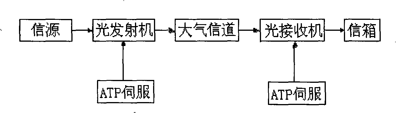
[0032] Existing wireless laser communication system structure, such as figure 1 shown. The system includes an ATP servo system and an optical transmitter, an atmospheric channel, and an optical receiver connected in sequence, and the ATP servo system is respectively connected with the optical transmitter and the optical receiver. The optical transmitter includes a signal input processing and modulation circuit, a semiconductor laser emitting light source and its driving power, and an optical emitting system. Optical receiver includes receiving optical system, photodetector, signal processing, demodulation and output circuit. ATP servo control system includes signal analog / digital conversion and processing, control computer and interface, signal digital / analog conversion and processing, control and correction network, servo drive unit, feedb...


PUM


Abstract

The present invention discloses a free space MIMO optical communication system based on the vertical layered space-time coding, wherein the free space MIMO optical communication system comprises a transmission terminal system and a receiving terminal system. The transmission terminal system comprises an information source, a distributing device, a layered space-time coder, a modulating and driving circuit array, a laser array and an optical transmission antenna array which are connected in series. The receiving terminal system comprises a channel estimator, and an optical receiving antenna array, a detector array, a linear decision feedback equalizer, a layered space-time coder / decoder, a multiplexer and an information sink which are connected in series. The optical transmission antenna array is composed of a plurality of pairs of parallel transmission antennae which are independent from each other. The optical receiving antenna array is composed of a plurality of pairs of optical receiving antennae which are independent from each other. The number of the optical receiving antennae is larger than or equal to that of the transmission antennae. The system according to the invention increases the speed of the communication code and the information flow-rate of the system. The communication is not affected by the atmosphere random channel.

Description

technical field [0001] The invention belongs to the technical field of wireless communication, relates to a laser communication system, in particular to a free space MIMO optical communication system based on vertical layered space-time coding. Background technique [0002] Communication is divided into wired communication and wireless communication. Wired communication includes cable communication and optical fiber communication; wireless communication includes microwave communication and laser communication. [0003] Wired communication requires the erection of communication lines, which has a long construction period, high cost, and difficult construction. Wireless communication is not restricted by lines, and has incomparable advantages over wired communication, so it has developed rapidly. At present, the amount of communication information is increasing rapidly, and there is an urgent need to expand network bandwidth resources and increase communication traffic to me...

Claims


Application Information

Patent Timeline
Patent Type & Authority Applications(China)
IPC IPC(8): H04B10/04H04B10/06H04B10/40H04L1/06
Inventor 柯熙政王惠琴
Owner XIAN UNIV OF TECH
Why Eureka
Try Eureka