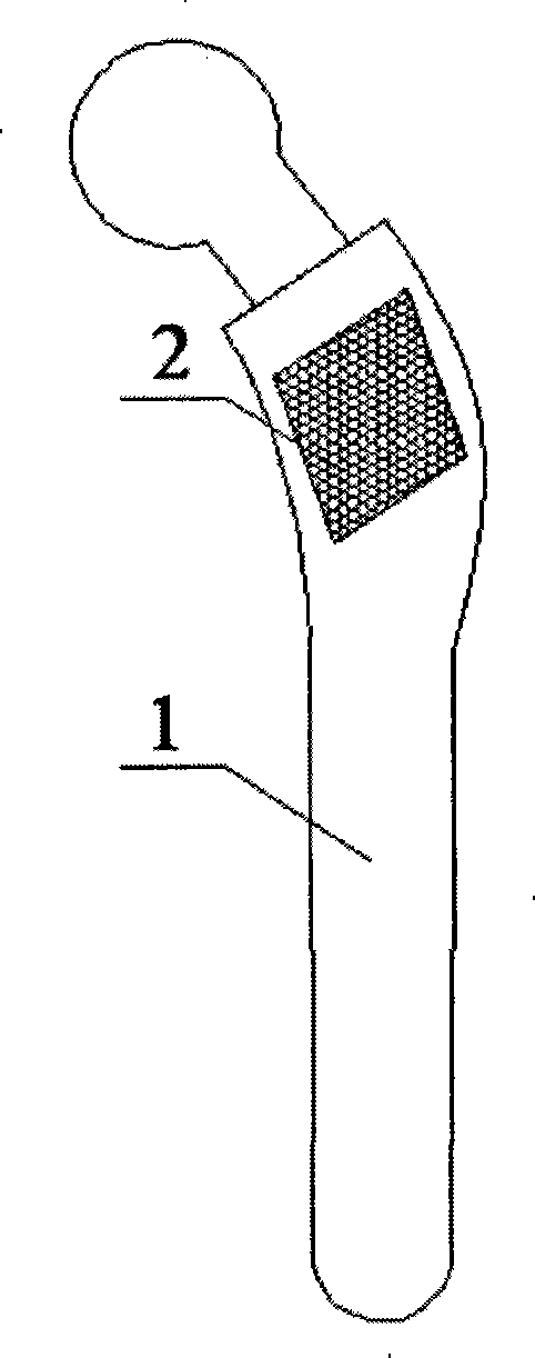
Local spatial grid structure artificial joint prosthesis and preparation method thereof
A grid structure, artificial joint technology, applied in prostheses, joint implants, joint implants and other directions, can solve problems such as damage to the mechanical properties of prostheses, and achieve the effect of protecting high-strength mechanical properties
- Summary
- Abstract
- Description
- Claims
- Application Information
AI Technical Summary
Problems solved by technology
Method used
Image
Examples
Embodiment 1
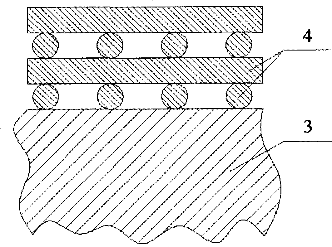
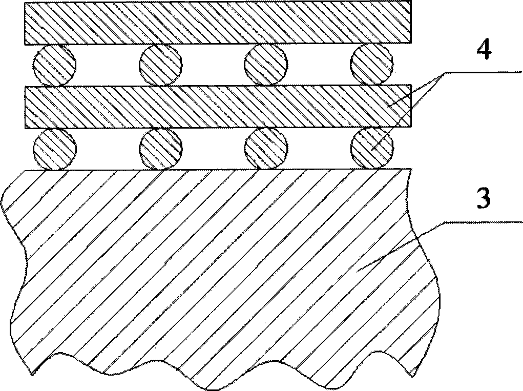
[0036] First, weave titanium metal fiber wires with a diameter of 50 μm on a titanium plate with a length of 30 mm, a width of 20 mm, and a thickness of 3 mm. The weaving shape is an orthogonal grid structure, and the distance between the titanium wires is 200 μm; The titanium plate is placed in a vacuum sintering furnace for high-temperature sintering. The vacuum degree of the sintering furnace is 1×10 -3 Pa, the furnace temperature is room temperature, the furnace temperature is raised to 1200°C, and the heating rate is 5°C / min. During the sintering process, a pressure of 5 MPa is applied to the titanium plate with a titanium wire braided structure, and the heat preservation and pressure are maintained for 2 hours. Cool the furnace to room temperature to obtain a titanium plate with a surface grid structure; use laser welding technology to weld the titanium plate with a surface grid structure to the predetermined position on the artificial joint prosthesis to form a partial g...
Embodiment 2
[0038] First, weave a titanium metal fiber wire with a diameter of 500 μm on a titanium plate with a length of 50 mm, a width of 40 mm, and a thickness of 5 mm. The weaving shape is an orthogonal grid structure, and the distance between the titanium wires is 1200 μm; The titanium plate is placed in a vacuum sintering furnace for high-temperature sintering. The vacuum degree of the sintering furnace is 1×10 -3 Pa, the furnace temperature is room temperature, the furnace temperature is raised to 1400°C, and the temperature rise rate is 10°C / min. During the sintering process, a pressure of 2 MPa is applied to the titanium plate with a titanium wire braided structure, and the temperature is maintained for 1 hour. Cool the furnace to room temperature to obtain a titanium plate with a surface grid structure; use laser welding technology to weld the titanium plate with the surface grid structure to the predetermined position on the artificial joint prosthesis to form a partial grid st...
Embodiment 3
[0040]First, weave titanium metal fiber wires with a diameter of 300 μm on a titanium plate with a length of 40 mm, a width of 30 mm, and a thickness of 4 mm. The weaving shape is an orthogonal grid structure, and the distance between the titanium wires is 700 μm; The titanium plate is placed in a vacuum sintering furnace for high-temperature sintering. The vacuum degree of the sintering furnace is 1×10 -3 Pa, the furnace entry temperature is room temperature, the furnace temperature is raised to 1300°C, and the temperature rise rate is 7.5°C / min. During the sintering process, a pressure of 1.5MPa is applied to the titanium plate with a titanium wire braided structure, and the heat preservation and pressure holding are carried out for 1.5h. Finally, the furnace temperature is cooled to room temperature to obtain a titanium plate with a surface grid structure; using laser welding technology, the titanium plate with the surface grid structure is welded to the predetermined positi...
PUM
| Property | Measurement | Unit |
|---|---|---|
| size | aaaaa | aaaaa |
| diameter | aaaaa | aaaaa |
| thickness | aaaaa | aaaaa |
Abstract
Description
Claims
Application Information
 - R&D
- Intellectual Property
- Life Sciences
- Materials
- Tech Scout
- Unparalleled Data Quality
- Higher Quality Content
- 60% Fewer Hallucinations
Browse by: Latest US Patents, China's latest patents, Technical Efficacy Thesaurus, Application Domain, Technology Topic, Popular Technical Reports.
© 2025 PatSnap. All rights reserved.Legal|Privacy policy|Modern Slavery Act Transparency Statement|Sitemap|About US| Contact US: help@patsnap.com


