Plasma processing device
A plasma and processing device technology, applied in the field of plasma processing devices, can solve the problems of destroying the lattice integrity of the polished surface, polluting the polished surface, sub-surface damage, etc., and achieves good polishing effect, control uniformity, and lattice integrity. Effect
- Summary
- Abstract
- Description
- Claims
- Application Information
AI Technical Summary
Problems solved by technology
Method used
Image
Examples
Embodiment 1
[0022] Polishing rate experiment of quartz glass:
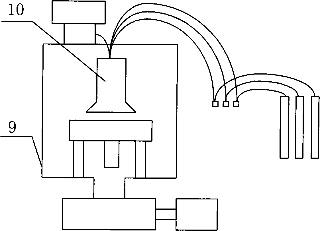
[0023] Step 1: The quartz workpiece to be polished is cleaned, and the standard RCE process is mainly used for cleaning. Open the vacuum chamber and place the workpiece on the workpiece table; use the exhaust system to reduce the vacuum in the vacuum chamber to 10 -3 Pa.
[0024] Step 2: Fill in the working gas, argon (10%~90%), oxygen (0%~90%) sulfur hexafluoride (1%~90%), and the vacuum degree reaches between 0.1Pa~100Pa; turn on the radio frequency Power supply for components, adjustable between 10 watts and 200 watts.
[0025] Step 3: Adjust the size and position of the magnetic field, and process and obtain two samples under the conditions of no magnetic field and applied magnetic field respectively.
[0026] Step 4: Process for about 1 hour, turn off the power, and turn off the working gas. Take out the workpiece, and test the surface roughness and etching depth of the workpiece.
[0027] Comparing the two processe...
Embodiment 2
[0029] Step 1: The quartz workpiece to be polished is cleaned, and the standard RCE process is mainly used for cleaning. Open the vacuum chamber and place the workpiece on the workpiece table; use the exhaust system to reduce the vacuum in the vacuum chamber to 10 -3 Pa.
[0030] Step 2: Fill in the working gas, argon (10%~90%), oxygen (0%~90%) sulfur hexafluoride (1%~90%), and the vacuum degree reaches between 0.1Pa~100Pa; turn on the radio frequency Power supply for components, adjustable between 10 watts and 200 watts.
[0031] Step 3: Fix the magnetic field position. The magnetic field strengths were adjusted to be 200 mTesla, 400 mTesla, and 600 mTesla respectively, and 3 samples were processed respectively.
[0032] Step 4: The processing is the same (1 hour), turn off the power, and turn off the working gas. Take out the workpiece, test the surface roughness and etching depth of the workpiece respectively, and calculate the etching rate.
[0033] The results show t...
Embodiment 3
[0035] Step 1: The quartz workpiece to be polished is cleaned, and the standard RCE process is mainly used for cleaning. Open the vacuum chamber and place the workpiece on the workpiece table; use the exhaust system to reduce the vacuum in the vacuum chamber to 10 -3 Pa.
[0036] Step 2: Fill in the working gas, argon (10%~90%), oxygen (0%~90%) sulfur hexafluoride (1%~90%), and the vacuum degree is between 0.1Pa~100Pa; open Power supply for RF components, regulated between 10 watts and 200 watts.
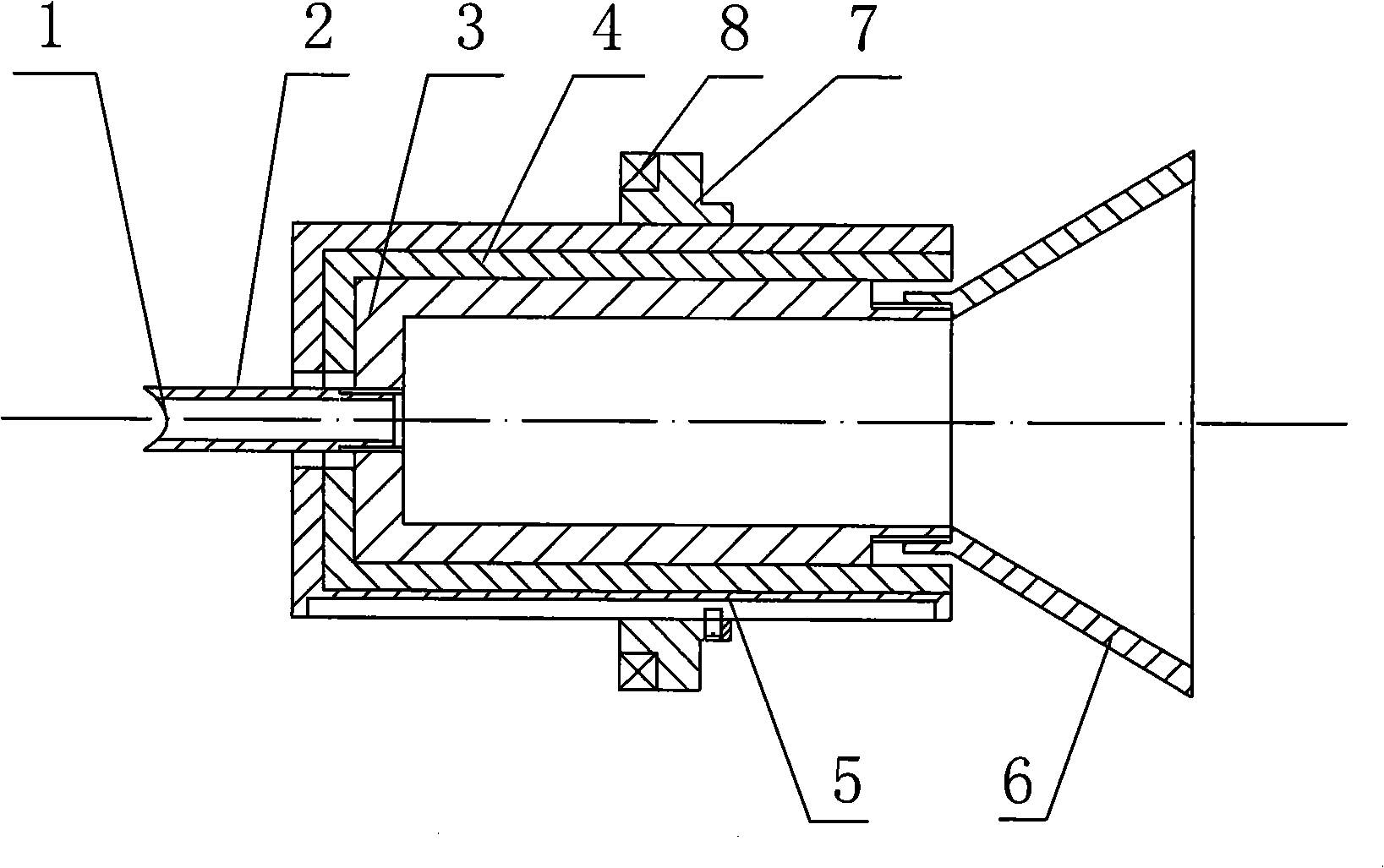
[0037] Step 3: Fix the position and size of the magnetic field, and use homogenizers without conicity (three).
[0038] Step 4: The processing time is the same (1 hour), three samples are processed under three different conic degrees, the radio frequency power supply is turned off, the working gas is turned off, and the workpiece is taken out.
[0039] Take multiple points on each workpiece to test the etching depth to reflect the uniformity of the plasma on the working surface. ...
PUM
 Abstract
Description
Claims
Application Information
 - R&D
- Intellectual Property
- Life Sciences
- Materials
- Tech Scout
- Unparalleled Data Quality
- Higher Quality Content
- 60% Fewer Hallucinations
Browse by: Latest US Patents, China's latest patents, Technical Efficacy Thesaurus, Application Domain, Technology Topic, Popular Technical Reports.
© 2025 PatSnap. All rights reserved.Legal|Privacy policy|Modern Slavery Act Transparency Statement|Sitemap|About US| Contact US: help@patsnap.com


