Manufacturing method of gate

A manufacturing method and gate technology, applied in the field of gate manufacturing, can solve the problems of semiconductor device leakage current increase, gate sidewall surface roughness, roughness sensitivity, etc., to achieve reduced leakage current, reduced roughness, The effect of enhancing sensitivity

Inactive Publication Date: 2012-12-12
SEMICON MFG INT (SHANGHAI) CORP +1
View PDF1 Cites 0 Cited by
  • Summary
  • Abstract
  • Description
  • Claims
  • Application Information

AI Technical Summary

Problems solved by technology

[0012] In the manufacturing method of the gate in the Chinese patent application document, a gate with a smaller line width can be formed through a subtractive process, but the process of etching the gate layer 5 to form the gate 5a generally uses anisotropic plasma Dry etching, so that the profile of the sidewall of the formed gate 5a is as vertical as possible to the surface of the semiconductor substrate 7; but the plasma dry etching also makes the surface of the sidewall of the gate relatively rough, The rough surface will cause the leakage current of the formed semiconductor device to increase; especially for the semiconductor device with a small gate line width, the leakage current is more sensitive to the roughness of the gate surface

Method used


Image

  • Manufacturing method of gate
  • Manufacturing method of gate
  • Manufacturing method of gate

Examples


Embodiment Construction

[0059] The specific embodiments of the present invention will be described in detail below in conjunction with the accompanying drawings.

[0060] Figure 8 It is a flow chart of the first embodiment of the gate manufacturing method of the present invention.

[0061] Such as Figure 8 The flow chart shown, step S100, provides a semiconductor substrate having a polysilicon layer thereon.

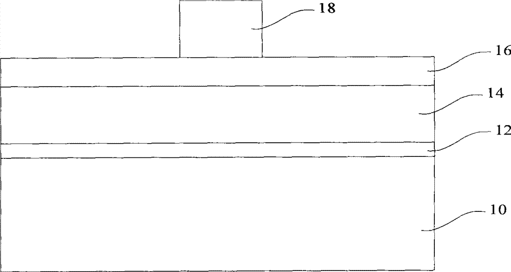
[0062] Such as Figure 9 The cross-sectional schematic diagram shown provides a semiconductor substrate 20, the material of the semiconductor substrate 20 can be one of single crystal silicon, polycrystalline silicon, and amorphous silicon, and the material of the semiconductor substrate 20 can also be a silicon germanium compound, The semiconductor substrate 20 may also be a silicon on insulator (Silicon On Insulator, SOI) structure or an epitaxial layer structure on silicon. N-type impurities or P-type impurities can be doped into the semiconductor substrate 20 to form N wells or P well...


PUM

PropertyMeasurementUnit
widthaaaaaaaaaa

Abstract

A method for making a grid electrode comprises the following steps that: a semiconductor substrate is provided with a multicrystal silicon layer; a metal layer is formed on the multicrystal silicon layer; visualization of the metal layer is carried out, and a grid electrode pattern is formed inside the metal layer; the multicrystal silicon layer uncovered by the grid electrode pattern is etched; during the etching process, a polymer layer is formed on the sidewall of the multicrystal silicon layer covered by the grid electrode pattern; and the polymer layer is removed to carry out the annealing process of the semiconductor substrate. The sidewall of the grid electrode formed by the method has less surface roughness.

Description

technical field [0001] The invention relates to the technical field of semiconductor manufacturing, in particular to a method for manufacturing a gate. Background technique [0002] With the continuous development of semiconductor manufacturing technology, the line width of the gate, which is used to measure the technological level of semiconductor manufacturing technology, is getting smaller and smaller; at present, the line width of the gate can reach 65nm or even smaller. A small gate line width can reduce the driving voltage of the formed semiconductor device, thereby reducing power consumption; in addition, a small gate line width can also reduce the size of the formed semiconductor device, improve integration, and increase the power consumption per unit area. The number of semiconductor devices reduces the cost. [0003] Figures 1 to 3 It is a schematic cross-sectional view of corresponding structures in each step of a conventional gate manufacturing method. Such as...

Claims


Application Information

Patent Timeline
Patent Type & Authority Patents(China)
IPC IPC(8): H01L21/28H01L21/336H01L21/8238
Inventor 张海洋刘乒马擎天
Owner SEMICON MFG INT (SHANGHAI) CORP
Why Eureka
Try Eureka