Process for manufacturing hot rolled steel strips by continuous casting and rolling middle bar strip

A technology of medium-thin slab continuous casting and hot-rolled strip steel, which is applied in heat treatment furnaces, metal rolling, heat treatment equipment, etc., can solve the problems of increased production cost of electricity, increased investment, and long buffer time, and achieve stable and consistent product performance , Large production capacity of the rolling mill, small temperature difference between the head and the tail of the steel strip

Active Publication Date: 2008-10-29
BAOSHAN IRON & STEEL CO LTD
View PDF0 Cites 19 Cited by
  • Summary
  • Abstract
  • Description
  • Claims
  • Application Information

AI Technical Summary

Problems solved by technology

At the same time, the temperature of the slab entering the furnace in the walking beam heating furnace is low, the latent heat of the slab cannot be fully utilized, and direct rolling cannot be realized
[0012] In comparison, the walking beam heating furnace is the most simple and mature, with less investment, low operation and maintenance costs, and easier to master, but it has certain restrictions on the single weight of the billet. If the single weight of the billet is too large, the furnace will be too wide , the investment increased a lot
[0013] The straight-through roller bottom tunnel furnace is used the most, and it has been proved to be reliable in production, with smooth process and flexible use, but it occupies a large area, which makes the production line too long and the maintenance cost is too high (mainly the regular replacement of heat-resistant rollers)
Induction heating furnace and hot coil box are relatively new technologies, with long buffer time, flexible heating temperature and heating depth, small footprint, but high maintenance costs, relatively large investment, for countries and regions with high electricity costs increase production costs
[0014] In the ISP process, due to the close connection between the roughing mill and the continuous casting machine, there are the following problems: the first cutting machine is arranged after the roughing mill, and the continuous casting machine and the roughing mill are connected by continuous casting slabs, and the production The process is difficult to control; since the continuous casting machine is in continuous low-speed production, it is required that the originally high-speed roughing unit should also be continuously produced at low speed and synchronously with the continuous casting machine. It is easy to deform under the action of the cast slab; without heating, there is a huge temperature difference between the edge and the middle of the slab, resulting in surface defects such as cracks on the edge of the steel plate
Same as the CSP process, there is a long tunnel roller hearth heating furnace, and the length of the entire production line increases

Method used


Image

  • Process for manufacturing hot rolled steel strips by continuous casting and rolling middle bar strip
  • Process for manufacturing hot rolled steel strips by continuous casting and rolling middle bar strip
  • Process for manufacturing hot rolled steel strips by continuous casting and rolling middle bar strip

Examples


Embodiment Construction

[0049] Preferred embodiments of the present invention will be described in detail below with reference to the accompanying drawings.

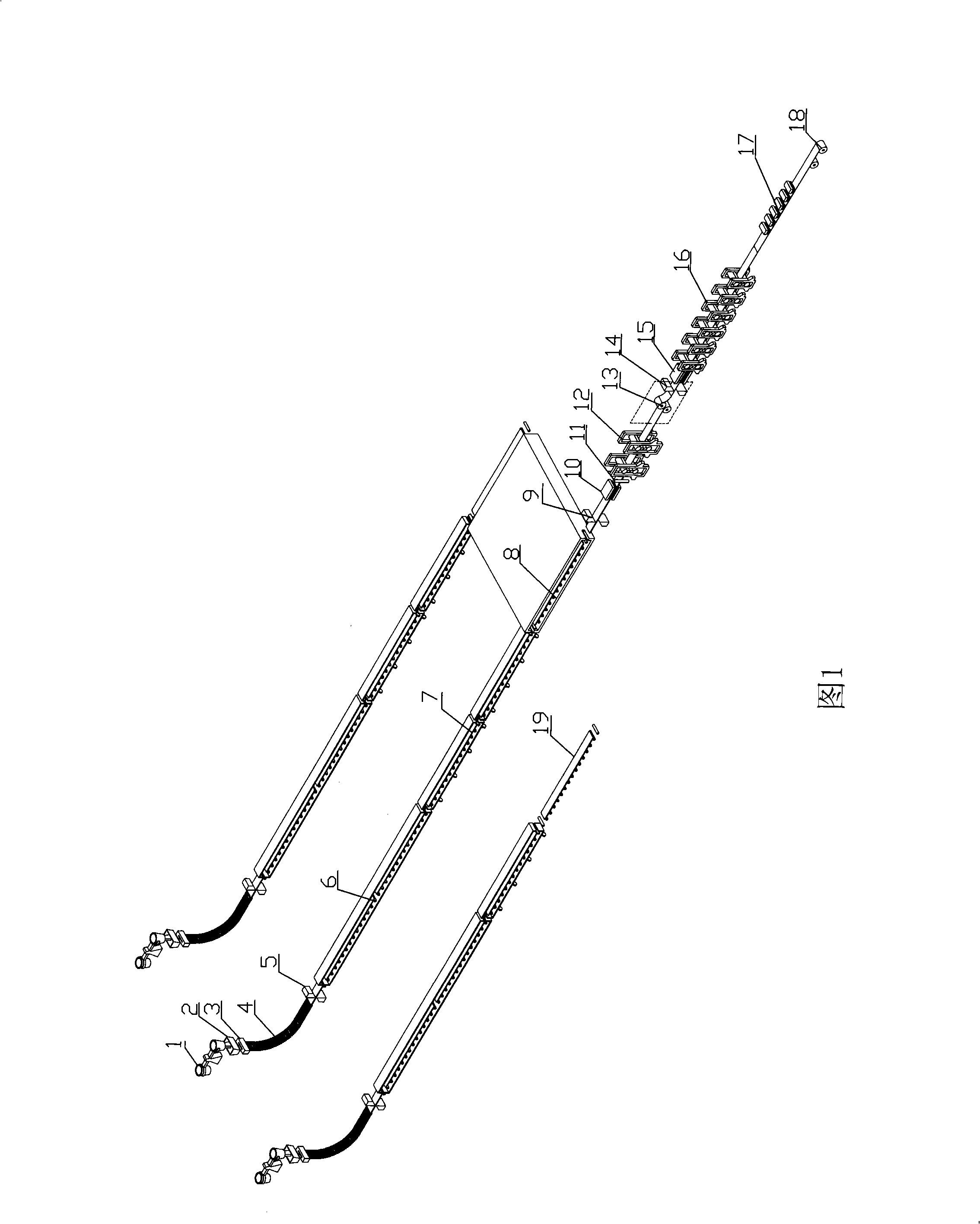
[0050] Fig. 1 shows the schematic diagram of the first preferred embodiment of the present invention, that is, the production line of hot-rolled strip produced by continuous casting and rolling of thin slabs from three-strand casting machines to a group of rolling mills at the same time. Wherein, the swinging section 7 behind the continuous casting machine 4 allows other strands and slabs to flow into the rolling line, sharing the rolling equipment in the subsequent step.

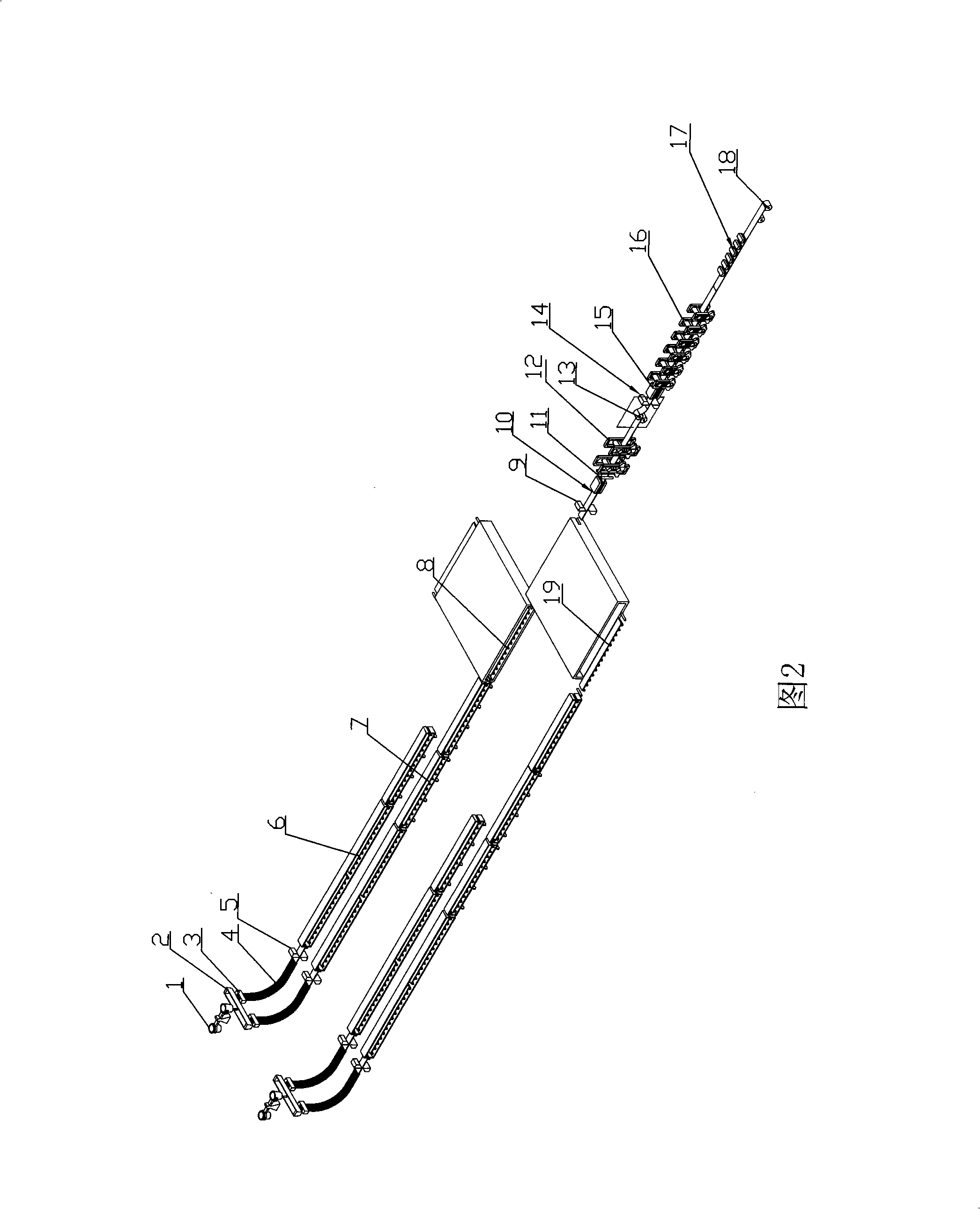
[0051] Fig. 2 shows the schematic diagram of the second preferred embodiment of the present invention, that is, the four-strand casting machine simultaneously feeds billets to a group of rolling mills to produce hot-rolled strip steel by continuous casting and rolling of thin slabs. Wherein, the two strands share one swing section 7, so that the other first strand cast slabs...


PUM

PropertyMeasurementUnit
thicknessaaaaaaaaaa
thicknessaaaaaaaaaa

Abstract

The invention discloses a continuous casting and tandem rolling method for producing hot rolling strip steel by using medium sheet billet, including the following steps: 1) liquid molten steel passes through a long nozzle from a ladle to be cast to a pouring box, flows through a submerged nozzle from the pouring box to be cast in a crystallizer of a continuous caster and is continuously cooled in the continuous caster to form a casting blank; 2) the casting blank enters a short tunnel roller hearth type heating furnace for heating; 3) a technology of converging a plurality of casting flows is adopted, one of the casting flows is in collineation with a rolling mill, the casting blank of other flows passes through a swinging section and is converged with the casting blank of the collinear flow, then passes through a walking beam and a holding zone of the roller hearth complex type heating furnace which is provided with a roller way and finally enters high pressure water for descaling; 4) the casting blank is prepared into an intermediate blank by rough rolling; 6) the intermediate blank carries out finish rolling into a steel strip with standard thickness; 7) the steel strip is cooled and coiled into the finished steel coil. The method can reduce investment, save energy resource, improve the quality of products, expand the varieties of the products and lower production cost.

Description

technical field [0001] The invention relates to the technical field of metallurgy, in particular to a method and equipment for producing hot-rolled strip steel by continuous casting and rolling of medium and thin slabs. Background technique [0002] The continuous casting and rolling technology is to connect two mature technologies, each of which is a system - continuous casting and continuous rolling through the connecting zone. However, there are many inconsistencies and mismatching factors between these two technologies, so an important feature of continuous casting and rolling technology is the emergence of the connection buffer concept and corresponding technical equipment. [0003] First of all, there is a big mismatch between the operating rates of continuous rolling and continuous casting. The operating rate of continuous rolling is very high, up to 80-90%, while the operating rate of continuous casting is relatively low, only 60-70%. [0004] Secondly, the producti...

Claims


Application Information

Patent Timeline
Patent Type & Authority Applications(China)
IPC IPC(8): B21B1/46B22D11/00B22D11/12C21D9/70C21D11/00
Inventor 徐荣军方园张立王喆陈应耀沈国强石振仓
Owner BAOSHAN IRON & STEEL CO LTD
Why Eureka
Try Eureka