Plasma film coating apparatus for particle surface modification

A particle surface, coating device technology, applied in gaseous chemical plating, metal material coating process, coating and other directions, can solve the problems of poor uniformity of polymer film, unsuitable for surface coating of fine particles, etc., to improve anti-thrombosis, The effect of improving electrical properties

Inactive Publication Date: 2008-10-29
TECHNICAL INST OF PHYSICS & CHEMISTRY - CHINESE ACAD OF SCI
View PDF0 Cites 5 Cited by
  • Summary
  • Abstract
  • Description
  • Claims
  • Application Information

AI Technical Summary

Problems solved by technology

[0004] The disadvantages of this device are: 1) the substrate can only be an object with a larger surface, which is not suitable for coating on the surface of fine particles
2) Since the plasma discharge at the edge between the parallel plates is different from the plasma discharge in the middle of the parallel plates, and the substrate is fixedly placed between the parallel plates, the resulting polymeric film has poor uniformity

Method used


Image

  • Plasma film coating apparatus for particle surface modification
  • Plasma film coating apparatus for particle surface modification
  • Plasma film coating apparatus for particle surface modification

Examples


Embodiment 1

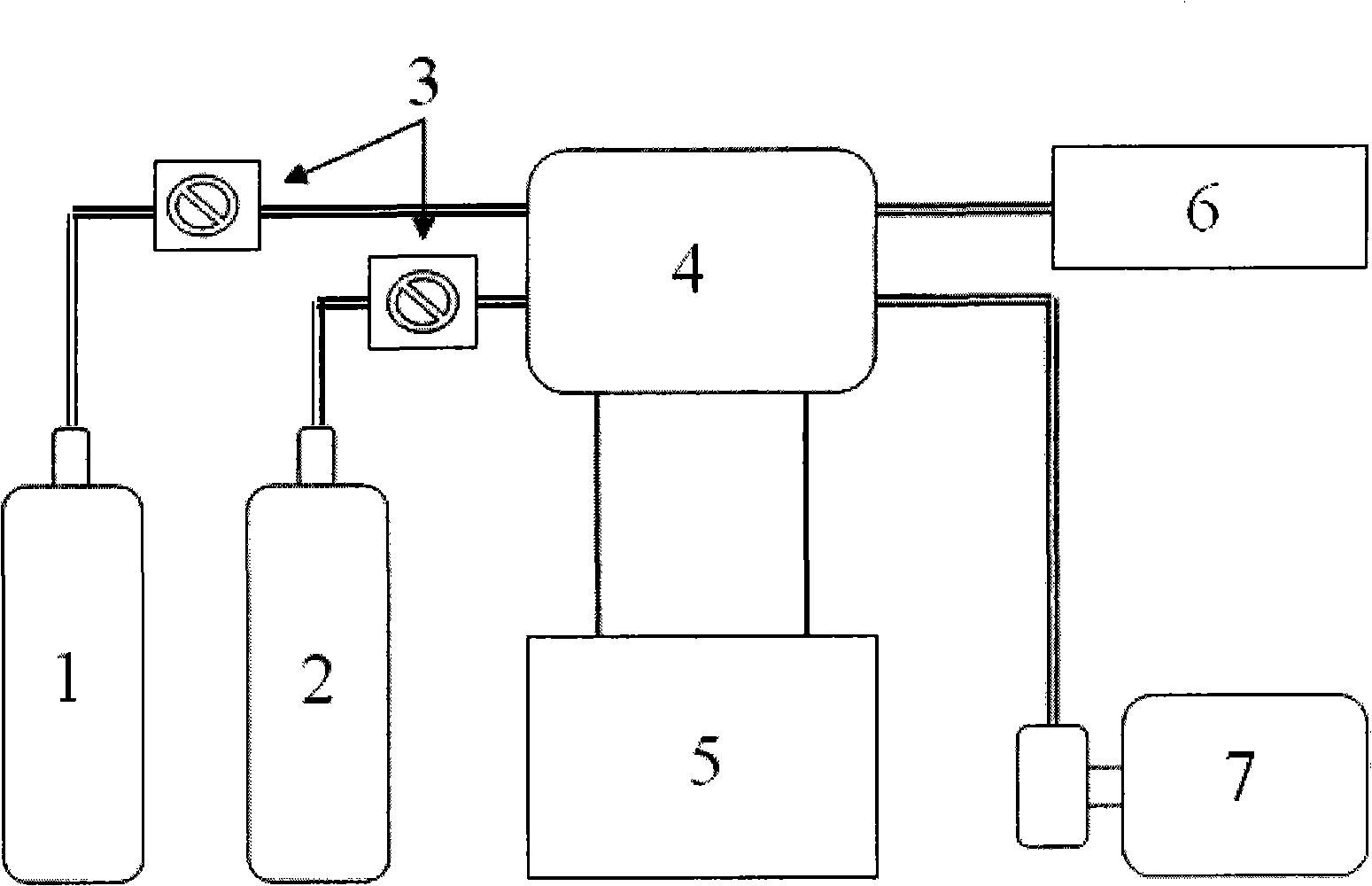
[0034] like figure 1 As shown, the device of this embodiment is mainly composed of a reaction chamber 4, a radio frequency power supply 5, a monomer vapor generating bottle 1, an argon gas bottle 2, a flow controller 3, a vacuum gauge 6 and a vacuum pump 7; the monomer vapor generating bottle 1. The argon gas bottle 2 and the vacuum pump 7 are respectively connected to the reaction chamber 4 through pipelines, and the pipelines connecting the monomer vapor generating bottle 1 and the argon gas bottle 2 to the reaction chamber 4 are respectively provided with a flow controller 3, and the radio frequency The power supply 5 is connected with a radio frequency discharge coil, and the radio frequency discharge coil is wound on the outer wall of the container of the reaction chamber 4 .

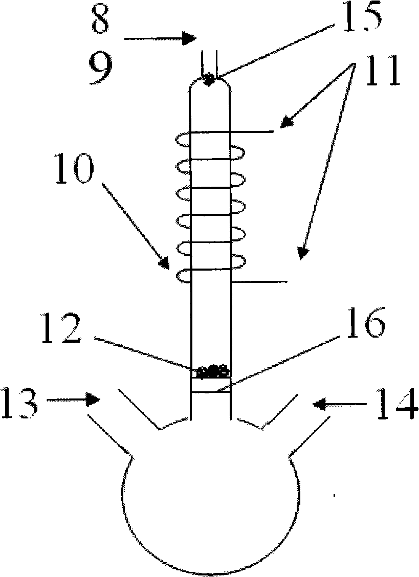
[0035] The reaction chamber 4 of this embodiment is a plasma polymerization reaction chamber 4 adopting the scheme of particle self-dispersing small glass tubes. like figure 2 As shown, the main...

Embodiment 2

[0042] The reaction chamber 4 of this embodiment adopts the scheme of magnetically stirring the upright cylindrical glass tube, and the rest of the parts except the reaction chamber 4 and the connection relationship between each part are consistent with the embodiment 1, and will not be repeated. The structure of the reaction chamber 4 in this embodiment will be described below.

[0043] like image 3 As shown, the reaction chamber 4 of this embodiment is an upright glass tube with a diameter of 100 mm and a length of 600 mm, and the sample is placed at the bottom of the glass tube. A magnetic stirrer is set just below the glass tube. There is a magnetic stirring blade 17 inside the glass tube, and the magnetic stirring blade 17 is installed at the bottom of the glass tube. The monomer vapor inlet 14 is located on the side wall near the bottom of the glass tube, and the top of the glass tube has an argon gas inlet 13 , a vacuum pump port 8 and a vacuum gauge port 9 . The radi...

Embodiment 3

[0048] The reaction chamber 4 of this embodiment adopts the motor-stirred horizontal glass tube scheme, and the rest of the parts except the reaction chamber 4 and the connection relationship between each part are consistent with the embodiment 1, and will not be repeated. The structure of the reaction chamber 4 in this embodiment will be described below.

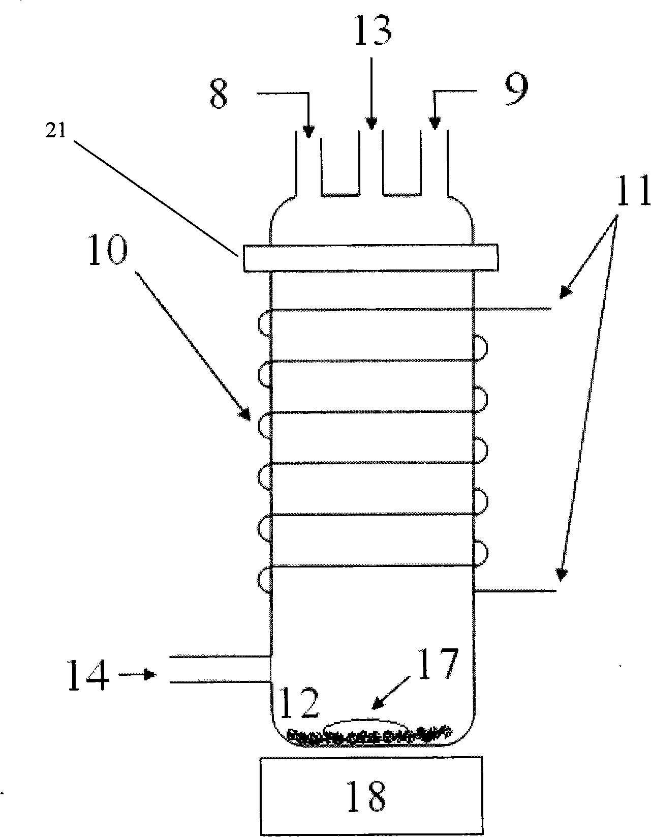
[0049] like Figure 4 As shown, the reaction chamber 4 in this embodiment is a horizontal glass tube with a diameter of 15 mm and a length of 1000 mm, and the sample particles 12 are placed on the inner wall of the lower side of the glass tube. A horizontal rotating shaft is installed in the glass tube, and the stirring blade is installed on the horizontal rotating shaft. The stirring motor drives the stirring blades to rotate through the horizontal rotating shaft. The stirring motor, the horizontal shaft and the stirring blades are all sealed in the glass tube. Argon inlet 13 , monomer vapor inlet 14 , vacuum gauge port...


PUM

PropertyMeasurementUnit
diameteraaaaaaaaaa
lengthaaaaaaaaaa
diameteraaaaaaaaaa

Abstract

The invention relates to a plasma coating device used for particle surface modification, which comprises a reaction chamber, a radio-frequency power supply, a monomer steam generating bottle, a dielectric gas bottle and a vacuum pump; the monomer steam generating bottle, the dielectric gas bottle and the vacuum pump are respectively connected with the reaction chamber through a pipeline, the radio-frequency power supply is connected with a radio-frequency discharge coil, and the radio-frequency discharge coil is wound on the outer wall of the container of the reaction chamber. The plasma coating device has the advantages that evenly controllable plasma coating on the particle surface can be realized; the components of the thin film are diversified; the thickness of the thin film is controllable between a few nanometers and a few micrometers; the thin film is of continuity, has no pinhole and can adopt a three-dimensional crosslinked way; specific thin film can be coated on the surface of the special particle.

Description

technical field [0001] The invention belongs to the technical field of material surface modification, in particular to a plasma coating device for particle surface modification. Background technique [0002] Plasma polymerization coating is a new type of coating method in which a glow discharge is performed in an organic gas, or a mixture of monomers and other gases, so that the monomers are excited to form active free radicals and then undergo polymerization reactions to form polymer films. Plasma polymerization is caused by energetic electron collisions to excite monomers, and does not require the presence of unsaturated bonds or specific functional groups, so some monomers that are usually difficult to polymerize or polymerize slowly become easy to polymerize, and the polymerization rate can be very fast . Almost all organic gaseous substances and even inorganic gaseous substances can be used as monomers for polymerization. Compared with the traditional polymerization m...

Claims


Application Information

Patent Timeline
Patent Type & Authority Applications(China)
IPC IPC(8): C23C16/513C23C16/448C08J7/16
Inventor 李来风黄荣进黄传军蔡方硕龚领会徐向东
Owner TECHNICAL INST OF PHYSICS & CHEMISTRY - CHINESE ACAD OF SCI
Why Eureka
Try Eureka