Display system based on blazed grating photomodulator

A technology of blazed gratings and light modulators, applied in diffraction gratings, optics, instruments, etc., can solve the problems of light energy loss in light splitting and light combining systems, achieve high resolution, high light source utilization, and improve collection efficiency

Inactive Publication Date: 2008-10-29
ACAD OF OPTO ELECTRONICS CHINESE ACAD OF SCI
View PDF0 Cites 4 Cited by
  • Summary
  • Abstract
  • Description
  • Claims
  • Application Information

AI Technical Summary

Problems solved by technology

DLP is one of the most successful all-digital display technologies, suitable for theaters and rear-projection TVs, but due to the use of UHP (Ultra High Pressure Mercury Lamp) and xenon lamps as light sources, its light splitting and light combining systems cause a large loss of light energy. The energy utilization rate is only 20% to 30%
GLV is the only successful color display technology based on the principle of diffraction. It has a high light utilization rate and can produce large-screen projection images by using a laser light source. Most of the energy of the diffracted light, therefore, the highest theoretical diffraction efficiency of the GLV that uses the first-order diffracted light to produce a picture is only 40.5%

Method used


Image

  • Display system based on blazed grating photomodulator
  • Display system based on blazed grating photomodulator
  • Display system based on blazed grating photomodulator

Examples


Embodiment 1

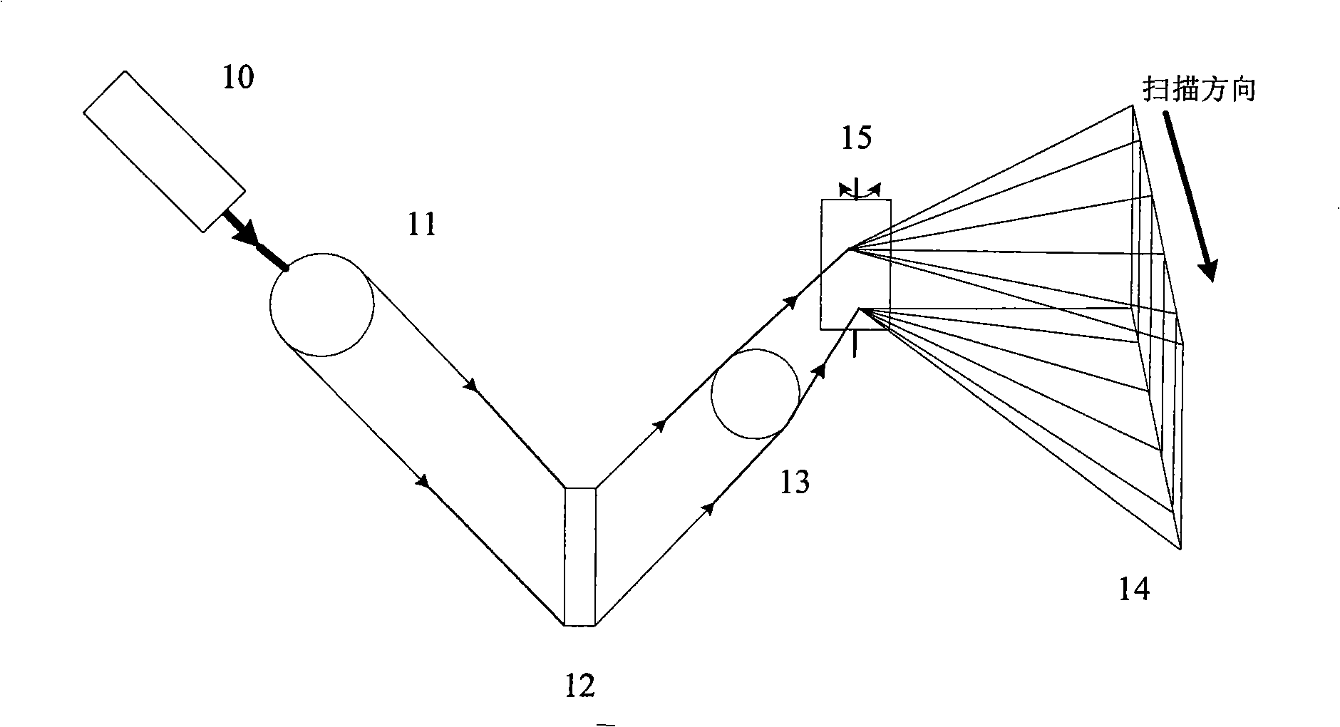
[0037] Such as figure 1 As shown, the display system based on the linear array MEMS blazed grating light modulator of the present invention is realized, which specifically includes: a light source 10; on the optical path at the light outlet of the light source 10, a lens for beam shaping and shim lighting is set 11. A blazed grating light modulator 12 for reflecting light beams is set on the output light path of the illumination lens group 11, and a projection lens device 13 is set on the reflection light path of the blazed grating light modulator 12. The projection lens A projection screen 14 is arranged in front of the output of the device 13 . The blazed grating light modulator 12 is a linear array blazed grating light modulator, and the system also includes a rapidly rotating array mirror 15 located between the projection lens device 13 and the projection screen 14, and the array mirror 15 transmits the light emitted by the projection lens device 13 reflected onto the pro...

Embodiment 2

[0042] On the basis of embodiment 1, different from embodiment 1 is:

[0043] The blazed grating light modulator 12 is a linear array blazed grating light modulator; the pixel unit of each blazed grating is composed of three sub-pixels, and the three sub-pixels respectively have a blaze angle corresponding to red, green and blue light, and the blazed grating light The modulator 12 controls the three sub-pixels of each pixel unit to change its blaze angle and maintain the blaze angle for outputting the required brightness; the linear array blazed grating light modulator and the vibrating mirror act in coordination to create a blaze angle on the projection screen. Realize scanning imaging.

[0044] Such as Figure 8 As shown, each sub-pixel has only one blaze angle, the direction 8 is the projection direction, that is, the light emission direction of the blazed grating, and the monochromatic light 6 is incident perpendicular to the grating surface 5. When the blazed grating pix...

Embodiment 3

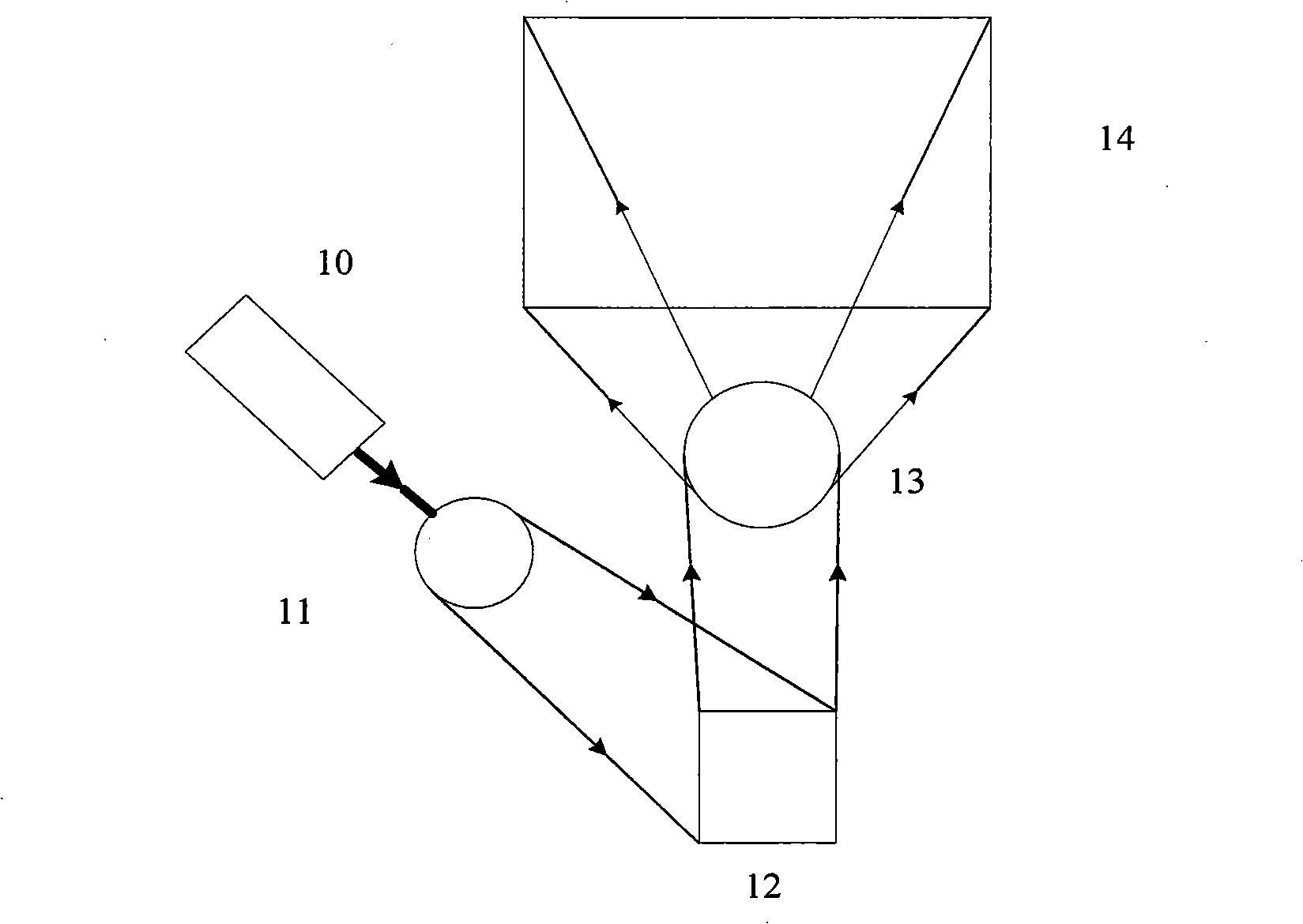
[0047] Such as figure 2 As shown, the display system based on the MEMS area blazed grating light modulator is realized, which specifically includes: a light source 10; on the optical path at the light outlet of the light source 10, a lens 11 for beam shaping and shimming is arranged, and A blazed grating light modulator 12 for reflecting light beams is arranged on the output light path of the illumination lens group 11, and a projection lens device 13 is set on the reflected light path of the blazed grating light modulator 12, and the projection lens device 13 outputs A projection screen 14 is arranged in front of the end; the blazed grating light modulator 12 is an area array blazed grating light modulator, and each pixel unit of the blazed grating has three blaze angles corresponding to red, green and blue light respectively, and the blazed grating light modulator 12 Control each pixel unit to change the blaze angle in time division for display according to red, green and b...


PUM


Abstract

The invention discloses a display system based on a blazed grating light modulator, which comprises a light source (10), an illuminating lens device (11) arranged on a path of rays at the light emission port of the light source and used for reshaping light beams and shimming, the blazed grating light modulator (12) arranged on the output path of rays of the illuminating lens device (11) and used for reflecting the light beams and a projection lens device (13) arranged on the reflection path of rays of the blazed grating light modulator (12), and the emergent light of the projection lens device (13) is launched onto a projection screen (14). The display system of the invention has high utilization rate of the light source, higher brightness and higher resolution factor, and the diffraction efficiency of work, namely, the utilization rate of luminous energy can achieve above 90 percent.

Description

technical field [0001] The present invention relates to a display device, in particular to a display system based on a blazed grating light modulator controlled by a Micro-Electrical-Mechanical System (MEMS for short). Background technique [0002] Existing display technologies can be divided into two categories: active luminescence and passive luminescence. [0003] Active luminescent display technologies include cathode ray tube (CRT), plasma panel (PDP), surface conduction emission (SED), carbon nanotube field emission (CNT) and organic electroluminescent diode (OLED), etc.; passive luminescent display technologies include liquid crystal Display (LCD), liquid crystal display on silicon (LCOS), digital micromirror device display (DMD), interferometric modulation iMoD (Interfer-Omitric-Modulation Device, referred to as iMoD) display and grating light valve (GLV) display, etc. Among them, in the passive light-emitting display technology, LCOS will lose 50% of the energy of ...

Claims


Application Information

Patent Timeline
Patent Type & Authority Applications(China)
IPC IPC(8): G03B21/14G02B26/08G02B5/18G02F1/01
Inventor 毕勇王斌赵江山亓岩成华郑光房涛周翊颜博霞宫武鹏
Owner ACAD OF OPTO ELECTRONICS CHINESE ACAD OF SCI
Why Eureka
Try Eureka