
Double-frequency band lamination medium loading helical antenna

A medium-loaded, helical antenna technology, applied in antennas, resonant antennas, independent antenna unit combinations, etc., can solve the problem that the antenna cannot achieve dual-band operation, achieve good directivity and circular polarization performance, and reduce the impact , the effect of reducing the size

Inactive Publication Date: 2008-12-03
SOUTH CHINA UNIV OF TECH
View PDF0 Cites 19 Cited by
  • Summary
  • Abstract
  • Description
  • Claims
  • Application Information

AI Technical Summary

Problems solved by technology

[0014] In addition, Oliver Leisten also proposed a variety of different design and processing methods for the dielectric-loaded quadrifilar helical antenna. However, the antenna has not yet been able to work in dual frequency bands
GPS handheld terminal antennas that can work in both GPS L1 and L2 dual frequency bands have been rarely reported so far, and media-loaded helical antennas that can work in dual frequency bands have not been reported in any literature or patents so far

Method used


Image

  • Double-frequency band lamination medium loading helical antenna
  • Double-frequency band lamination medium loading helical antenna
  • Double-frequency band lamination medium loading helical antenna

Examples


Embodiment 1

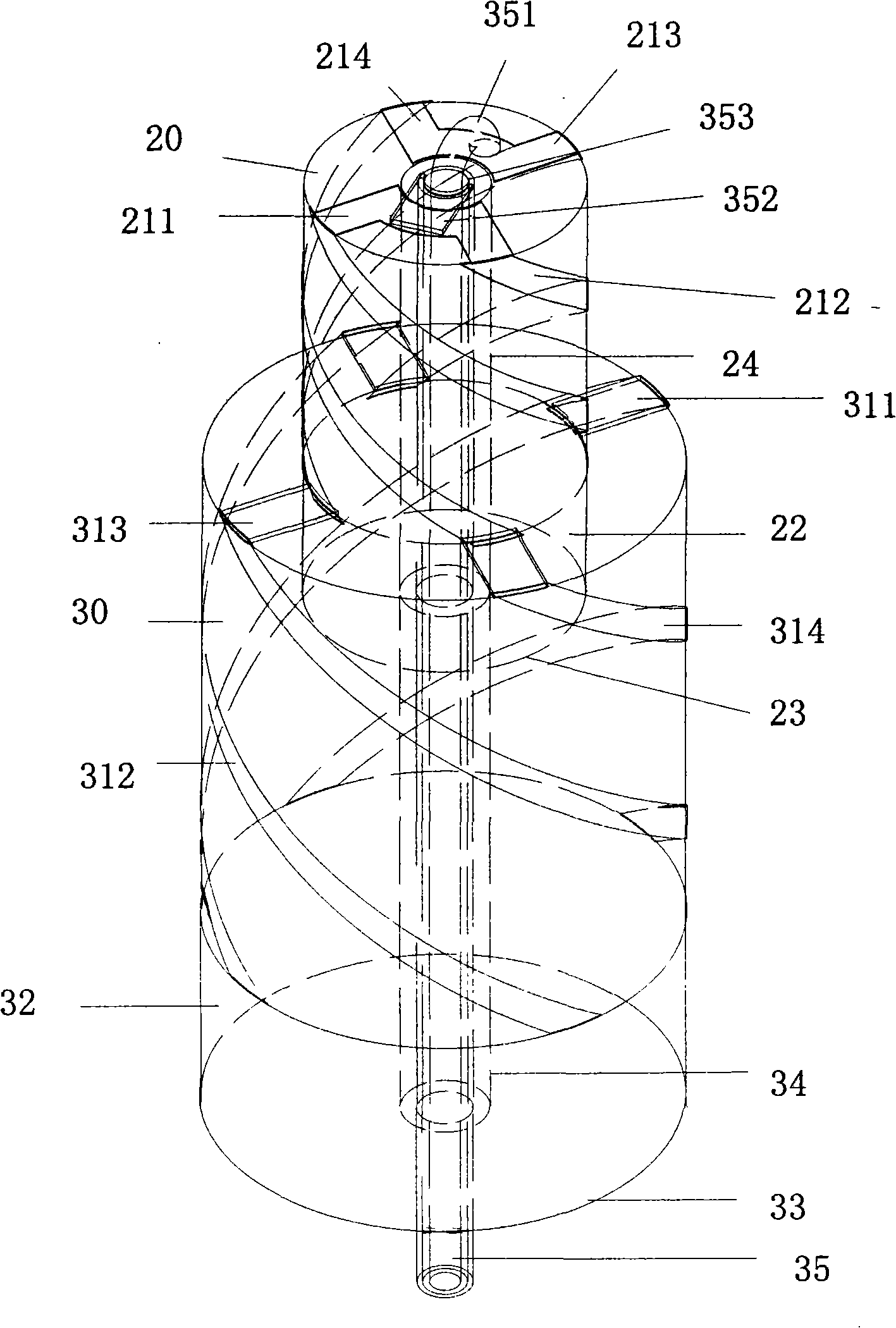
[0045] The specific structure of the antenna is as figure 1 As shown, the metal layer 22 on the columnar body 20 is all inserted into the top of the columnar body 30, and the two are closely attached to form an integral structure.

[0046] The radiating metal sheets 211, 212, 213, 214 extend in a helical path along the side of the columnar body 20, but they have different lengths. The pitches of the radiating metal sheets 211 and 213 are slightly larger than the pitches of the radiating metal sheets 212 and 214, so that The length of the radiating metal sheets 211 and 213 can be made to be 0.45λ 1 , slightly shorter than half the wavelength; the length of the radiating metal sheets 212 and 214 is 0.55λ 1 , slightly longer than half a wavelength, where λ 1 is the wavelength of the first working frequency band of the antenna; the radiating metal sheets 311, 312, 313, 314 extend along the side of the columnar body 30 in a helical path, but they have different lengths, and the p...

Embodiment 2

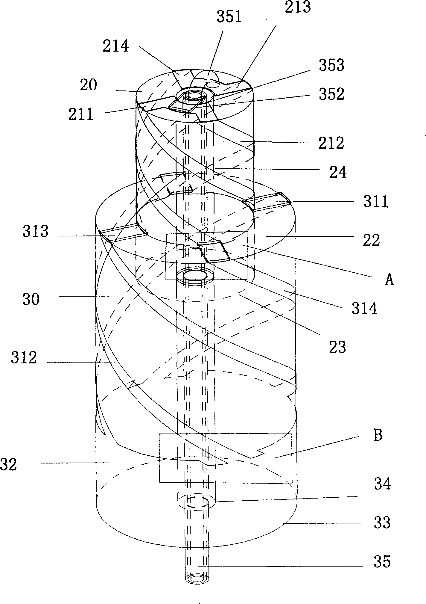
[0050] The specific structure of the antenna is as figure 2 As shown: the metal layer 22 on the outer surface of the bottom circumference of the columnar body 20 is completely inserted into the top of the columnar body 30, and the two are closely attached to form an integral structure.

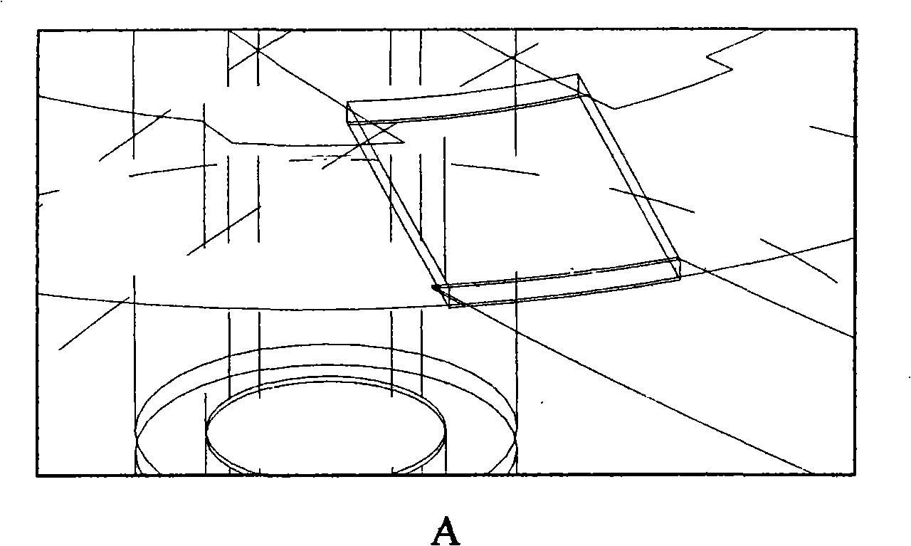
[0051] The radiating metal sheets 211, 212, 213, 214 extend in a helical path along the side of the columnar body 20, and they have the same pitch. In order to realize that the length of the radiating metal sheets 212 and 214 is about 0.05λ longer than the radiating metal sheets 211 and 213 1 , two small grooves (such as image 3 shown), where λ 1 Be the wavelength of the first operating frequency band of the antenna; similarly, the radiating metal sheets 311, 312, 313, 314 extend along the side of the columnar body 30 according to a helical path, and they have the same pitch, so that the length of the radiating metal sheets 312 and 314 is approximately 0.05λ longer than radiating metal she...

Embodiment 3

[0054] The specific structure of the antenna is as figure 1 Shown: the columnar body 20 is made of a dielectric material with a dielectric constant of 7.0, and the electrical length of the metal layer 22 is 0.31λ 1 ; The columnar body 30 is made of a dielectric material with a dielectric constant of 6.0, and the electrical length of the metal layer 32 is 0.27λ 2 The diameter ratio of the columnar body 30 to the columnar body 20 is 1.5, and the height ratio is 1.43. The metal layer 22 on the outer surface of the bottom circumference of the columnar body 20 is all inserted into the top of the columnar body 30, and the two are closely fitted to form an overall structure.

[0055] In order to realize the 90° phase difference between the radiating metal sheets 211, 212, 213, 214, the radiating metal sheets 211 and 213 extend in a spiral along the side of the columnar body 20 in a straight line, around the length of the columnar body 20 0.48λ 1 , while the radiating metal sheets 2...


PUM


Abstract

The invention provides a dual-band stacking medium loading spiral antenna, comprising two coaxial cylinder bodies with the upper part and the lower part stacked together; the sections of the bottom surface and the bottom part of the two cylinder bodies are provided with metal layers respectively, and the top ends thereof are respectively provided with four metal sheets with different lengths; one end of each metal sheet respectively extends radially from the center of the cylinder body to the circumference of the top surface and then to the metal layer axially in the spiral path from the surface of the metal sheet; the opposite surfaces of two adjacent metal sheets of the upper cylinder bodies are connected as two groups of antennas; the four metal sheets of the upper cylinder body and the lower cylinder body are respectively connected on the top end surface of the lower cylinder body; the dual-band stacking medium loading spiral antenna also comprises a cable which is embedded inside the through hole of the axle center and comprises an insulation body; the surface of the insulation body is covered by a conductive shield layer and the center thereof is provided with a feed-in needle; two ends of the feed-in needle extend out of the through hole; the top end of the conductive shield layer is connected with a group of the antennas of the upper cylinder body; the top end of the feed-in needle is connected with the other group of antennas of the upper cylinder body; the metal layers of the bottom surfaces of the upper cylinder body and the lower cylinder body respectively contact with the horizontal corresponding sections of the conductive shield layer. The antenna of the invention has small dimension and good performance.

Description

technical field [0001] The invention relates to an antenna, in particular to a stacked medium-loaded helical antenna structure that can work in dual frequency bands, effectively reduce the size of the antenna, and is suitable for handheld terminals. Background technique [0002] At the beginning of this century, with the free opening of GPS (Global Positioning System) to the civilian field, GPS has developed into a rapidly growing industry. At present, the civil field of GPS has included land transportation, ocean transportation, civil aviation, communication, surveying and mapping, construction, mining, agriculture, power system, medical application, scientific research, home appliances, entertainment and many other fields. In 2007, my country's GPS has entered a full-blown period. The rapid development of the GPS industry has affected the development of other parallel industrial chains and made them overlap and merge, making a large number of handheld terminal devices wit...

Claims


Application Information

Patent Timeline
Patent Type & Authority Applications(China)
IPC IPC(8): H01Q1/38H01Q21/24H01Q5/00H01Q9/27G01S5/02G01S19/01H01Q21/30
Inventor 褚庆昕刘沙
Owner SOUTH CHINA UNIV OF TECH
Learn More