
Process for manufacturing tap body

A manufacturing method and faucet technology, applied in the direction of valve details, engine components, valve housing structure, etc., can solve problems such as failure to form innovation and breakthrough, difficult to eradicate, etc., to achieve easy control of the manufacturing process, saving usage, tightness and Good corrosion resistance

Inactive Publication Date: 2008-12-10
林铨鸿
View PDF1 Cites 15 Cited by
  • Summary
  • Abstract
  • Description
  • Claims
  • Application Information

AI Technical Summary

Problems solved by technology

[0004] Obviously, although the above-mentioned methods have carried out new modularization treatment on the main shell of the faucet, the traditional casting, die-casting and other processes are still used in the processing and manufacturing of each component, which has not actually formed a real faucet. Innovation and breakthrough, so it is difficult to eradicate many of the aforementioned drawbacks

Method used


Image

  • Process for manufacturing tap body
  • Process for manufacturing tap body

Examples


Embodiment 1

[0038] Example 1: A 4-inch faucet body for a double-handle washbasin

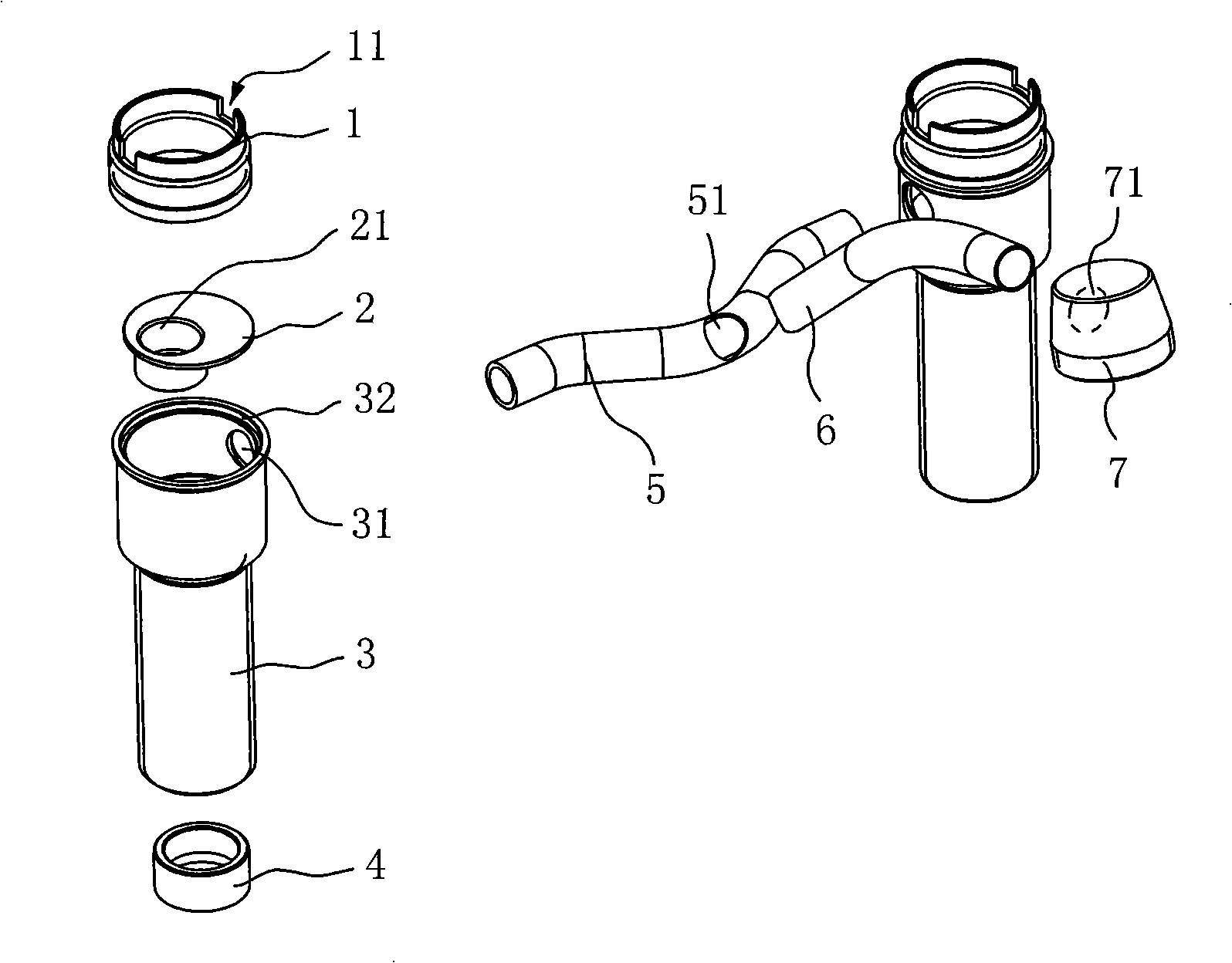
[0039] Such as figure 1 As shown, the body of the 4-inch double-handle faucet includes two pin components and a water outlet component, and the two pin components are symmetrically welded and fixed to both ends of the water outlet component.

[0040] Wherein, each pin assembly further includes a positioning tube 1, and two square slotted holes 11 symmetrically distributed along the radial direction for positioning are opened on the side wall of the top end, and the positioning tube 1 is processed and formed by stainless steel pipe material; Water pipe 3, the radial dimension of its upper end is larger than the radial dimension of the lower end and the two ends pass through to form a water flow channel, a side hole 31 is provided on the side wall of the upper end, and a hole 31 is provided on the inner wall of the upper end to match the outer wall of the lower end of the positioning pipe 1. Ring groove 32, ...

Embodiment 2

[0052] Example 2: 8-inch kitchen faucet body with double handles

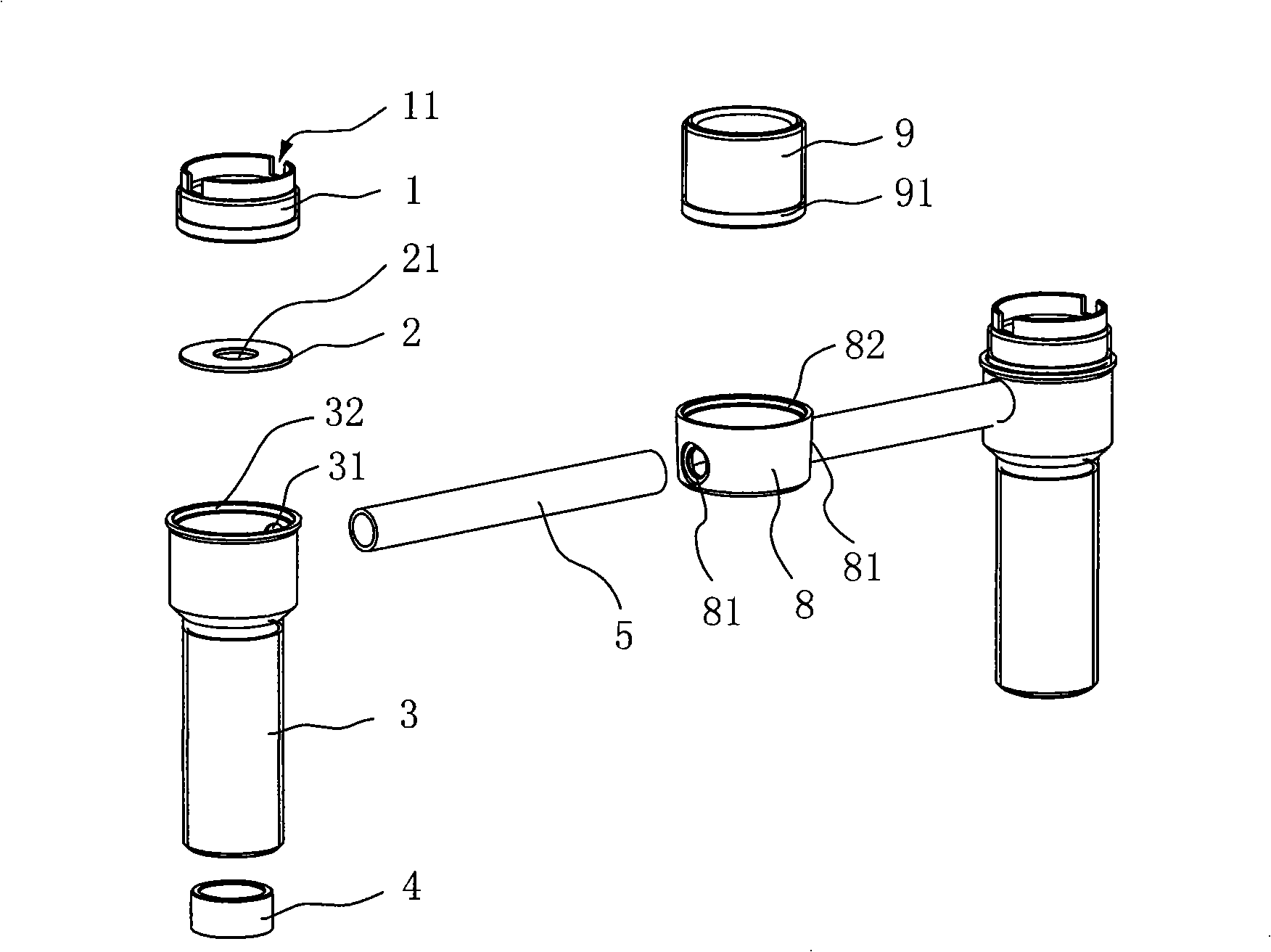
[0053] Such as figure 2 As shown, the body of the 8-inch double-handle faucet includes two pin components and a water outlet component, and the two pin components are respectively symmetrically welded and fixed to both ends of the water outlet component. Wherein, the specific structure, processing method and process, and welding operation sequence of each pin assembly are also similar to those in Embodiment 1, so details are not repeated here.

[0054] The difference is that the water outlet assembly in this embodiment includes: a faucet pipe 8, which penetrates up and down to form a water flow channel, and two side holes 81 are opened radially and symmetrically on its outer wall, and a ring is opened on the inner wall of the upper end. Groove 82, the faucet pipe 8 adopts stainless steel pipe material to be formed by cold stamping through a mold; two connecting pipes 5, the respective two ends of which are re...


PUM


Abstract

The invention discloses a manufacturing method for water faucet bodies, which comprises: step1, stainless steel pipes and / or stainless steel sheets are used respectively for processing and forming pin components and effluent components of the faucet body; step2, the processed and formed pin components and the effluent components are welded one by one in sequence to form the complete water faucet body in an assembly way; step3, the polishing and the electroplating treatment are carried out on the welded water faucet body. The invention avoids problems of bad quality, low material utilization, energy consumption, environment pollution, and the like produced by the traditional casting and hot forging, simplifies the manufacturing technique, and leads the processing and manufacturing processes to be controllable, thus improving the production efficiency and the yield significantly. As no expensive expenditure on forming dies is needed, the manufacturing method for the water faucet bodies saves the materials and reduces the production cost obviously; meanwhile, the method produces less negative influence to the surrounding environment, meets the requirements of energy-saving and environmental protection, and is very suitable for the wide substitution and application within the industry.

Description

technical field [0001] The invention relates to a method for manufacturing a faucet body, in particular to a method for manufacturing a stainless steel faucet body, and belongs to the field of hardware product manufacturing and processing. Background technique [0002] At present, most of the existing faucet bodies on the market are made of brass, cast iron and other materials, and are generally formed by sand casting or hot forging. However, the integrally formed body through casting inevitably has many bad defects such as trachoma, lack of material, cracks, etc., and the internal surface of the product is relatively rough, and particles such as sand cores are likely to remain, causing internal blockage of water outlet and accumulation of dirt. For the hot forging treatment method, there are also problems such as low material utilization efficiency and high production cost. It is particularly worth noting that casting and hot forging are traditional high-energy-consuming p...

Claims


Application Information

Patent Timeline
Patent Type & Authority Applications(China)
IPC IPC(8): B23P15/00F16K27/00
Inventor 林铨鸿
Owner 林铨鸿
Learn More