Production method of frequency domain transmission function shape dynamic tuning optical spectrum wave filter

A spectral filter and transfer function technology, applied in the coupling of optical waveguides, transmission systems, electromagnetic wave transmission systems, etc., can solve the problems of low yield, complexity, lack of flexibility, etc., to reduce insertion loss, simple manufacturing process , the effect of excellent flexibility

Inactive Publication Date: 2008-12-10
BEIJING JIAOTONG UNIV
View PDF0 Cites 4 Cited by
  • Summary
  • Abstract
  • Description
  • Claims
  • Application Information

AI Technical Summary

Problems solved by technology

At present, in the DWDM transmission system, due to the attenuation of the optical fiber, the gain of the erbium-doped fiber amplifier (EDFA), the insertion loss of the dispersion compensation module (DCM), and the gain or loss of other optical components are different with the signal wavelength, making DWDM The signal power and signal-to-noise ratio among the channels of the system are unbalanced, which leads to the degradation of the transmission quality of the DWDM system
Although a static gain flattening filter (GFF) has been used in the DWDM system to equalize the optical power between channels, the residual power imbalance will continue to accumulate and increase with the increase of cascaded links, generally within 20 amplifiers After cascaded applications, the gain unevenness of fiber a

Method used


Image

  • Production method of frequency domain transmission function shape dynamic tuning optical spectrum wave filter
  • Production method of frequency domain transmission function shape dynamic tuning optical spectrum wave filter
  • Production method of frequency domain transmission function shape dynamic tuning optical spectrum wave filter

Examples


Embodiment 1

[0033] A method for making a frequency-domain transfer function shape dynamically tuned spectral filter:

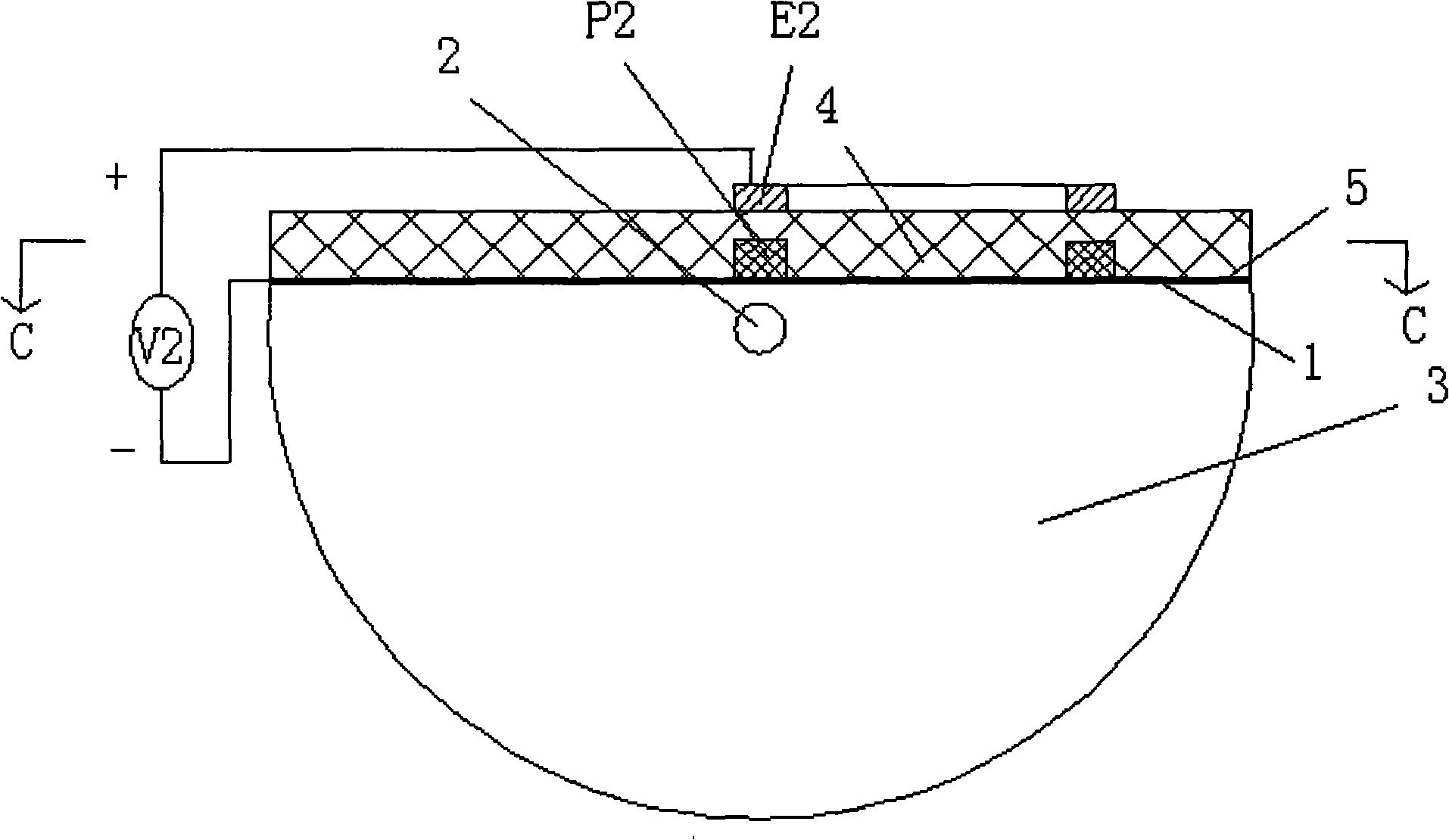
[0034] In step 1, a step-type single-mode fiber with a fiber core 2 having a diameter of 1 μm is selected, and the length of the step-type single-mode fiber is 1 m.

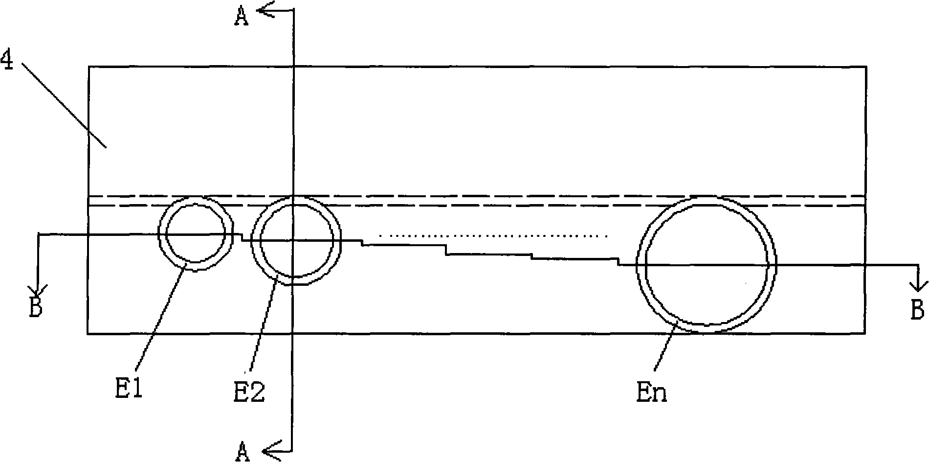
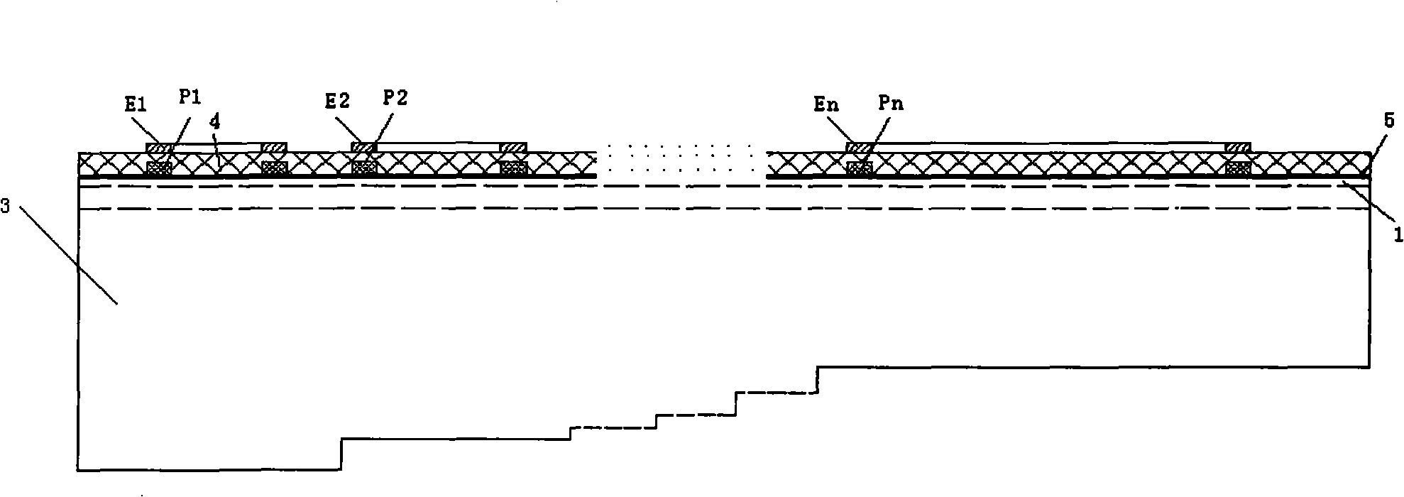
[0035] Step 2: Axially grind the middle part of the cladding 3 of the step-type single-mode optical fiber in step 1, the grinding length is 0.5 cm, and grind to the nearest point of 0.5 μm from the fiber core 2, and then polish, and the unground parts at both ends are used as Frequency-domain transfer function shapes for dynamically tuned pigtails of spectral filters.

[0036] In step 3, a layer of ITO electrode 5 is plated on the polished optical fiber axial grinding plane 1 by magnetron sputtering, and the thickness of the ITO electrode is 50 nm.

[0037] Step 4, on the ITO electrode 5, use a spin coater to spin coat a layer of 1 μm thick disperse red 13 / polymethyl methacrylate film with a high electro-op...

Embodiment 2

[0043] A method for making a frequency-domain transfer function shape dynamically tuned spectral filter:

[0044] In step 1, a step-type single-mode fiber with a fiber core 2 having a diameter of 10 μm is selected, and the length of the step-type single-mode fiber is 5 m.

[0045]Step 2: Axially grind the middle part of the cladding 3 of the step-type single-mode optical fiber in step 1. The grinding length is 5 cm, and it is ground to a point 5 μm closest to the fiber core 2, and then polished. The unpolished parts at both ends are used as the frequency domain Transfer function shape for dynamic tuning of spectral filter pigtails.

[0046] In step 3, a layer of ITO electrode 5 is plated on the polished optical fiber axial grinding plane 1 by vacuum evaporation method, and the thickness of the ITO electrode is 80 nm.

[0047] Step 4: Spin-coat a 10 μm-thick disperse red 1 / polycarbonate film with a high electro-optic coefficient on the ITO film using a spin coater, and then et...

Embodiment 3

[0053] A method for making a frequency-domain transfer function shape dynamically tuned spectral filter:

[0054] In step 1, a step-type single-mode fiber with a fiber core 2 having a diameter of 5 μm is selected, and the length of the step-type single-mode fiber is 2.5 m.

[0055] Step 2: Axially grind the middle part of the cladding 3 of the step-type single-mode optical fiber in step 1, the grinding length is 3 cm, and grind to a distance of 2 μm from the nearest point of the optical fiber core 2, and then polish, and the unpolished parts at both ends are used as the frequency Domain transfer function shape for dynamically tunable pigtails of spectral filters.

[0056] In step 3, a layer of ITO electrode 5 is plated on the polished optical fiber axial grinding plane 1 by ion plating method, and the thickness of the ITO electrode is 100 nm.

[0057] Step 4, on the ITO film, apply a layer of 5 μm thick lanthanum-doped lead titanate / polymethyl methacrylate film with high elec...


PUM

PropertyMeasurementUnit
Diameteraaaaaaaaaa
Lengthaaaaaaaaaa
Thicknessaaaaaaaaaa

Abstract

The invention discloses a making method of a frequency domain transmission function shape dynamic tuning spectral filter, the making process of the making method is that an ITO electrode (5), a plurality of polymer micro-rings (P1, P2...Pn) with different radii, polymer claddings (4) and electrode round rings (E1, E2...En) are orderly arranged on the axial grinding plane (1) of a D-shaped fiber which is grinded; the polymer micro-rings with different radii are perpendicularly coupled with fiber cores (2); different bias voltages are applied on each of the polymer micro-rings (P1, P2...Pn) to change the resonance frequency of each of the polymer micro-rings (P1, P2...Pn), and the frequency domain transmission function shape of the filter is dynamically changed through adjusting the bias voltage (V1, V2...Vn) of the polymer micro-rings (P1, P2...Pn). The making method is suitable for making various dynamic flat-channel and power-equalization devices.

Description

technical field [0001] The invention relates to a manufacturing method of a frequency domain transfer function shape dynamic tuning spectrum filter, which belongs to the field of optical fiber communication. Especially suitable for dense wavelength division multiplexing (DWDM) dynamic channel equalization, gain flatness optimization and other technical fields. Background technique [0002] With the dual impetus of market demand and technological progress, DWDM optical fiber communication technology is developing towards ultra-long, ultra-high-speed, large-capacity and dynamically configurable networking. At present, in the DWDM transmission system, due to the attenuation of the optical fiber, the gain of the erbium-doped fiber amplifier (EDFA), the insertion loss of the dispersion compensation module (DCM), and the gain or loss of other optical components vary with the signal wavelength, making DWDM The signal power and signal-to-noise ratio among the various channels of th...

Claims


Application Information

Patent Timeline
IPC IPC(8): G02B6/34H04B10/17H04J14/02
Inventor 裴丽赵瑞峰祁春慧宁提纲阮乂董小伟刘俊杰卓安生
Owner BEIJING JIAOTONG UNIV
Why Eureka
Try Eureka