Internal combustion engine turbocharging system

A turbocharging system and internal combustion engine technology, applied in the direction of internal combustion piston engines, combustion engines, gas turbine devices, etc., can solve the problems of harsh working conditions, high cost, low boost pressure, etc., to achieve accelerated response, low cooling requirements, The effect of weight reduction

Inactive Publication Date: 2008-12-24
CHERY AUTOMOBILE CO LTD
View PDF0 Cites 10 Cited by
  • Summary
  • Abstract
  • Description
  • Claims
  • Application Information

AI Technical Summary

Problems solved by technology

Although the supercharger does not increase the exhaust back pressure of the engine, it needs to consume the power of the engine, and the boost pressure is generally low
Exhaust gas turbocharging will greatly increase the exhaust back pressure of the engine, and high-temperature exhaust gas must pass through the supercharger. The components of the turbine n

Method used


Image

  • Internal combustion engine turbocharging system

Examples


Embodiment 1

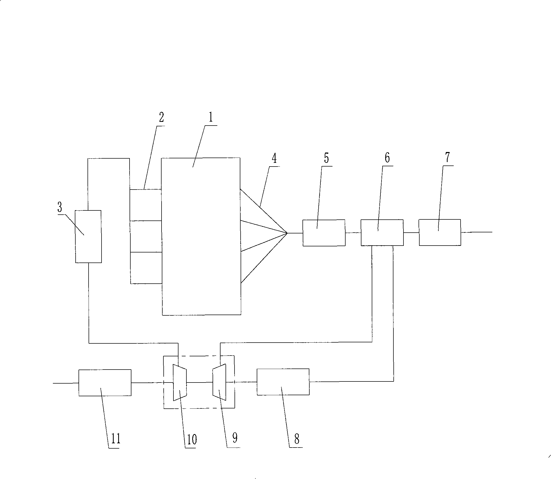
[0012] Example 1 as figure 1 As shown, it is a supercharged and intercooled internal combustion engine, including an internal combustion engine 1. The exhaust gas discharged from the internal combustion engine 1 enters the catalytic converter 5 after being collected through the exhaust manifold 4, and then passes through the evaporator 6, where the exhaust gas and the water in the evaporator are heated. Exchange, the temperature of the exhaust gas is greatly reduced, then enters the muffler 7, and finally is discharged into the atmosphere. The evaporator 6 fully absorbs the heat of the exhaust gas to generate high-temperature and high-pressure water vapor. The water vapor enters the turbine 9 of the supercharger through the transmission pipeline, drives the turbine to rotate at high speed, and drives the impeller of the coaxial compressor 10 to rotate. The water vapor passing through the turbine 9 enters the condenser 8 through the circulation pipeline, and is cooled in the co...

Embodiment 2

[0013] Embodiment 2 A supercharged internal combustion engine, including internal combustion engine 1, is characterized in that the present invention may not use an intercooler before the intake manifold, and the rest are the same as Embodiment 1.

Embodiment 3

[0014] Embodiment 3 A supercharged internal combustion engine, including the internal combustion engine 1, is characterized in that the supercharger can use various variable mechanisms to control the supercharging pressure, or use a simpler structure to change the turbocharger. Pressure. All the other are with embodiment 1 or 2.

[0015] The present invention is not limited to the structure of the above embodiment, it can also be used together with the exhaust gas turbocharger to form a compound supercharging system.


PUM


Abstract

The invention discloses a turbocharging system for an internal combustion engine, comprising the internal combustion engine which is provided with an evaporator capable of generating high-temperature and high-pressure water vapor on an exhaust pipe. The water vapor is guided into the turbine end of a supercharger by a pipeline to drive impellers of the turbo machine to rotate at a high speed and drive a coaxial air compressor to compress the air from an air filter, and the supercharged air is passed through an intake manifold of the internal combustion engine to enter the internal combustion engine. The water vapor discharged by the turbo machine is guided into a condenser that can condense the high-temperature and high-pressure water vapor into the water closed to the boiling point, and then is flowed back to the evaporator to circulate continuously. Because the water vapor is generated to drive the turbo machine and drive the coaxial air compressor to compress the air from the air filter, the exhaust back pressure can not be increased, and power of the internal combustion engine also can not be consumed. And an operating temperature is much lower, and a cooling requirement is lower, thereby compared with the exhaust turbocharging machine, the cost is reduced a lot; and the turbocharging system can be used together with the exhaust turbocharging machine.

Description

technical field [0001] The invention relates to a turbocharging system of an internal combustion engine, in particular to a turbocharging system driven by water vapor generated by the heat of the exhaust gas of the internal combustion engine. Background technique [0002] Automobiles have become a widely used means of transportation. Existing automobiles basically use internal combustion engines as power. At present, countries all over the world have invested a lot of manpower, material and financial resources to study how to reduce emissions and fuel consumption of internal combustion engines. But from the current technical point of view, although the invention of the internal combustion engine has a history of more than 100 years, its fuel utilization rate is still only 40%, and at the same time, about 40% of the fuel energy is discharged from the exhaust pipe in the form of heat. This will not only cause a lot of fuel waste, but also bring a lot of exhaust pollution and i...

Claims


Application Information

Patent Timeline
IPC IPC(8): F01N5/02F02B33/40F02B29/04F01N7/08F02B37/04F02C6/12F01N13/08
CPCY02T10/12
Inventor 刘庆
Owner CHERY AUTOMOBILE CO LTD
Why Eureka
Try Eureka