Plasma etching method
A plasma and etching technology, which is applied in the field of plasma, can solve the problems of inconstant time period and inability to obtain repeatability of plasma treatment, etc.
- Summary
- Abstract
- Description
- Claims
- Application Information
AI Technical Summary
Problems solved by technology
Method used
Image
Examples
no. 1 example
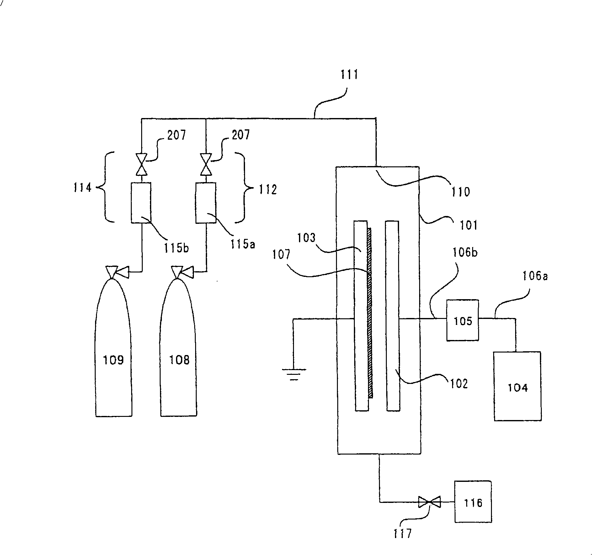
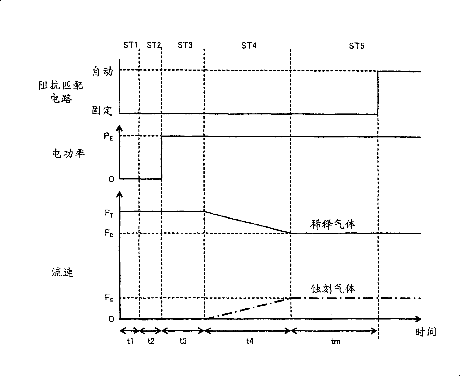
[0053] Next, a plasma etching method according to a first embodiment of the present invention will be described.
[0054] First, the dilution gas 108 is introduced into the plasma processing reaction chamber 101, and the flow rate of the dilution gas 108 is set to a constant flow rate value by the flow rate adjusting device 115a (ST1: dilution gas introduction step).
[0055] Next, the pressure in the etching reaction chamber 101 is kept substantially constant by the pressure relief valve 117 (ST2: pressure adjustment step). Here, the set pressure has a pressure value that satisfies desired etching conditions such as an etching rate in the etching step.
[0056] Then, electric power having a processing electric power value is applied from the power source 104 to the cathode electrode 102 to generate glow discharge plasma between the anode electrode 103 and the cathode electrode 102 (ST3: plasma generation step). Here, the processing electric power value is at least the minimu...
no. 2 example
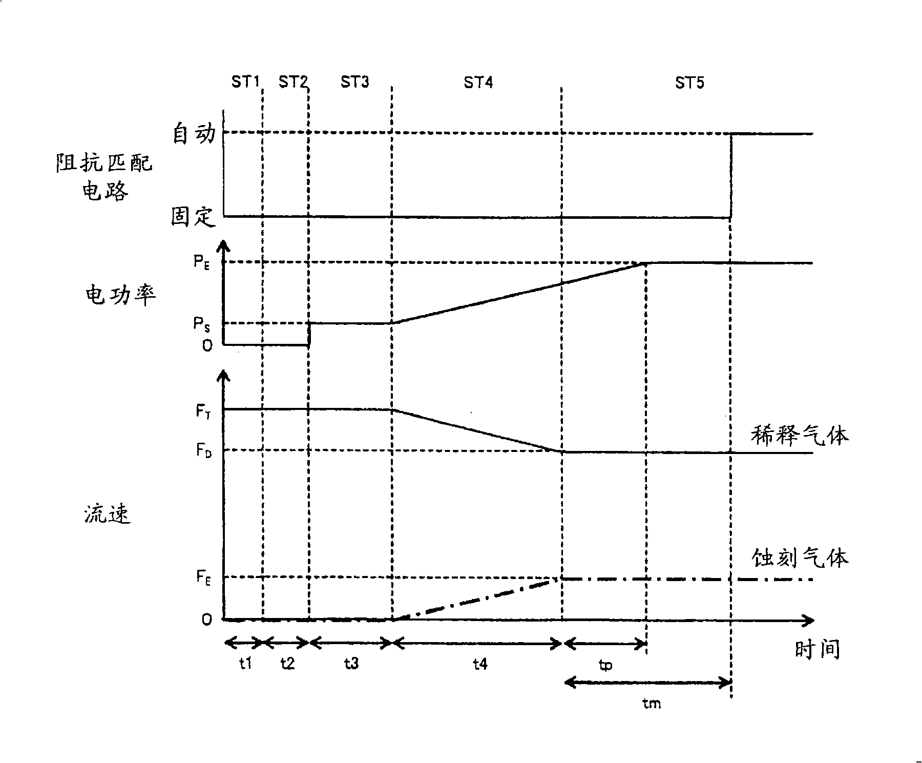
[0079] A plasma etching method according to a second embodiment of the present invention will be described based on the drawings. image 3 is a time chart of the plasma processing method according to the present embodiment.
[0080] The settings in the second embodiment are similar to those of the first embodiment except for the setting of electric power output from the power supply 104 .
[0081] In this embodiment, in the plasma generation step ST3, the electric power output from the power source 104 to the cathode electrode 102 is set to the initial electric power value P S , the output electric power value increases from the gas control step ST4 to the etching step ST5, and the output electric power value is fixed at the processing electric power value P in the etching step ST5 E .
[0082] The initial electric power value P in the plasma generation step ST3 S It must be at least electric power capable of causing glow discharge plasma between the anode electrode 103 and...
no. 3 example
[0092] In the first embodiment and the second embodiment, electric power is applied from a power source 104 to a pair of anode electrode 103 and cathode electrode 102 via an impedance matching circuit 105 . or, as in Figure 4 As shown, multiple pairs of anode electrodes 103 and cathode electrodes 102 can be connected to one impedance matching circuit 105 .
[0093] In this case, it is difficult to simultaneously generate glow discharge plasma between the respective anode electrodes 103 and cathode electrodes 102 of the plurality of pairs of electrodes. In other words, if glow discharge plasma is generated between some of the pairs of electrodes, the resistance between the electrodes becomes smaller. Therefore, electric power supplied between other electrodes is smaller and plasma is not generated between these electrodes.
[0094] To solve this problem, a voltage greater than the discharge start voltage must be applied between each pair of electrodes. Because of the greate...
PUM
 Abstract
Description
Claims
Application Information
 - R&D
- Intellectual Property
- Life Sciences
- Materials
- Tech Scout
- Unparalleled Data Quality
- Higher Quality Content
- 60% Fewer Hallucinations
Browse by: Latest US Patents, China's latest patents, Technical Efficacy Thesaurus, Application Domain, Technology Topic, Popular Technical Reports.
© 2025 PatSnap. All rights reserved.Legal|Privacy policy|Modern Slavery Act Transparency Statement|Sitemap|About US| Contact US: help@patsnap.com


