Engine oxygen-increasing pressure regulating energy-saving device

An energy-saving device and engine technology, which is applied to engine components, machines/engines, charging systems, etc., can solve problems such as the unsatisfactory effect of self-adaptive pressure regulation and oxygen increase, and achieve improved self-adaptive effect, accurate adjustment, and improved combustion. efficacy effect

Active Publication Date: 2010-08-25
SANMENXIA SUDA TRANSPORTATION ENERGY SAVING TECH
View PDF1 Cites 2 Cited by
  • Summary
  • Abstract
  • Description
  • Claims
  • Application Information

AI Technical Summary

Problems solved by technology

The Chinese patent No. 200720089140.6 discloses an energy-saving device for increasing the oxygen and pressure of the engine. The pressure regulating intake valve of the device adopts a spring and a regulating valve with an inclined end face. Due to the complex and changeable working conditions of the engine, the vacuum behind the throttle The temperature also changes accordingly, however, due to reasons such as the frictional resistance of the regulating valve, the effect of self-adaptive pressure regulation and oxygen increase is not very ideal.

Method used


Image

  • Engine oxygen-increasing pressure regulating energy-saving device
  • Engine oxygen-increasing pressure regulating energy-saving device
  • Engine oxygen-increasing pressure regulating energy-saving device

Examples


Embodiment 1

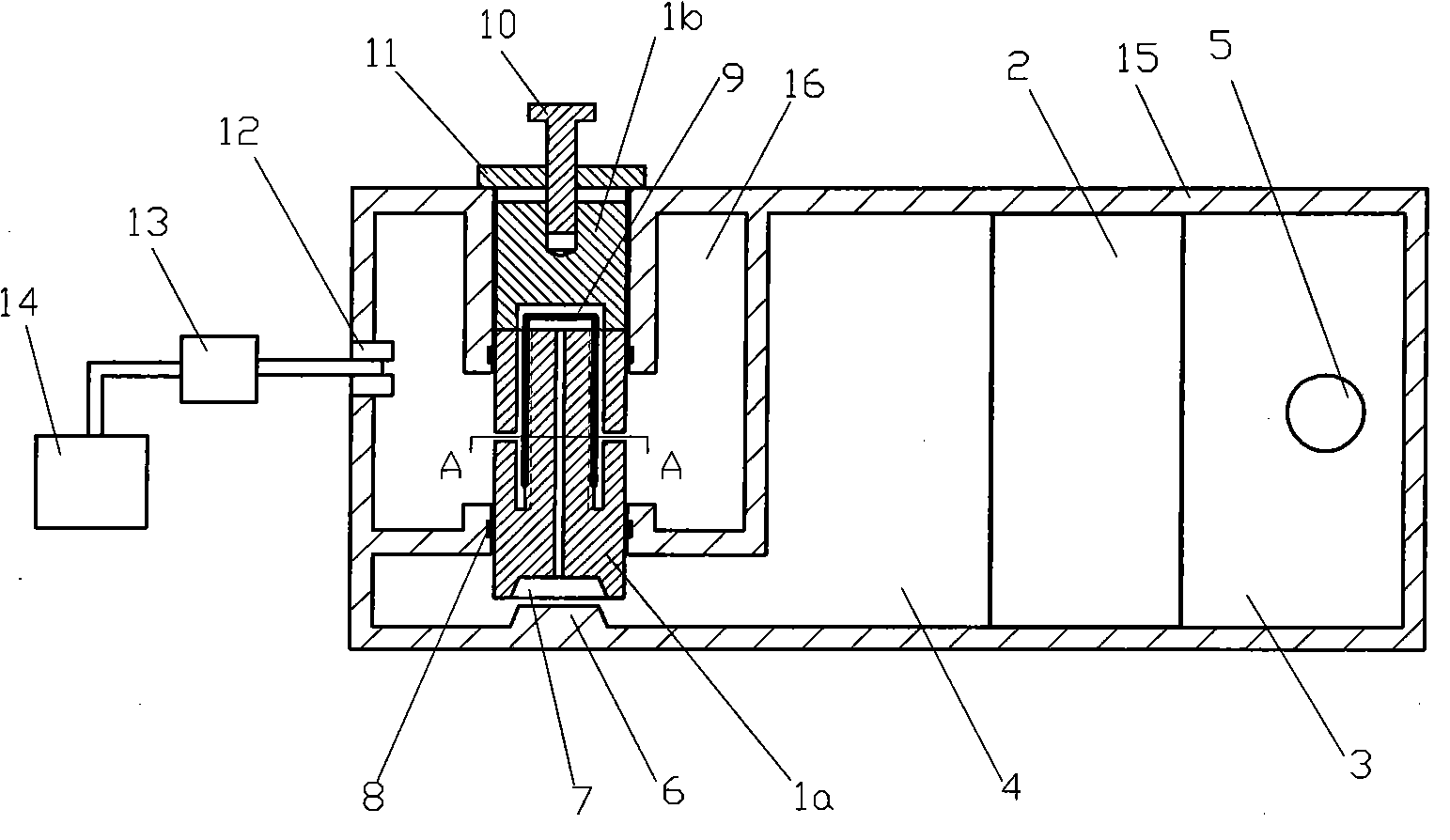
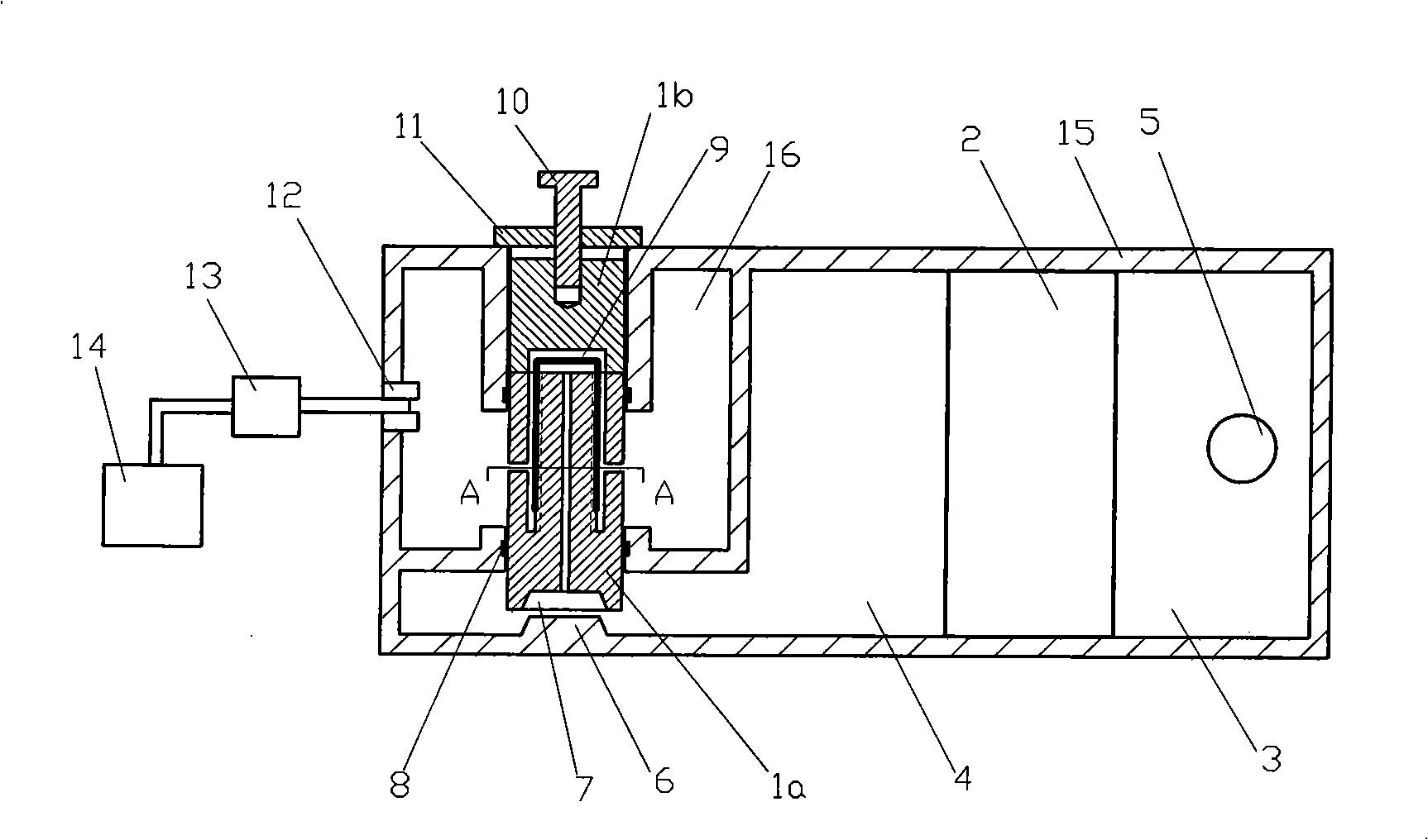
[0022] As shown in Figures 1 and 2, the engine oxygen-increasing and pressure-regulating energy-saving device of the present invention includes a box body 15, a gas filter device 2, and a gas flow regulating valve during implementation. The valve body of the gas flow regulating valve includes a valve seat 1b and a valve body. Head 1a. The gas filtering device 2 divides the inner cavity of the box body 15 into a pre-filter chamber 3 and a post-filter chamber 4, and a pressure regulating chamber 16 is set in the post-filter chamber 4, and the pre-filter chamber 3 is provided with The main air inlet 5 is provided with the main air outlet on the pressure regulating chamber, and the air outlet pipe card valve 12 is arranged at the main air outlet. The gas filtering device 2 can be made of layered macromolecular material, such as polyacrylonitrile ultrafiltration membrane, or a nitrogen filter. This embodiment directly adopts a nitrogen filter. It is arranged in the pre-filter cham...

Embodiment 2

[0025] The implementation of this example is basically the same as that of Example 1, except that the valve seat 1b and valve head 1a are made of copper or aluminum, and the cup-shaped thin-walled container is made of steel. Or a permanent magnet is set on the casing 15 to offset the gravity of the steel cup 9 and the frictional force between the steel cup 9 and the valve head 1a, so that the adaptive pressure regulation and oxygen increase effect is better; the gas filter 2 is arranged at intervals Several layers of polymer material filter layers, among which, the filter layer near the pre-filtration chamber 3 is made of polyacrylonitrile ultrafiltration membrane with a molecular cutoff of more than 5000, and the polyacrylonitrile ultrafiltration membrane can filter and remove part of nitrogen , increase the content of oxygen in the gas in the filtered chamber 4 .


PUM


Abstract

The present invention discloses an engine oxygen-increasing, pressure-regulating and energy-saving device which comprises a box body, a gas filtering apparatus and a gas flow regulating valve. The gas filtering apparatus divides the inner cavity of the box body into a cavity chamber before filtering and a cavity chamber after filtering. A pressure regulating cavity chamber is arranged in the cavity chamber after filtering. The cavity chamber before filtering is provided with a general air inlet. The pressure regulating cavity chamber is provided with a general air outlet. The general air outlet is communicated with the vacuum pipe of the air throttle of the engine. The gas flow regulating valve is arranged on the cavity wall of the pressure regulating cavity chamber and runs through the pressure regulating cavity chamber. The gas flow regulating valve is matched and connected with the cavity wall of the pressure regulating cavity chamber by screw threads. A sealing device is arranged at the position that the gas flow regulating valve and the pressure regulating cavity chamber are matched with each other. An indirect gas passage is arranged in the valve body of the gas flux regulating valve. The inlet of the gas passage is exposed outside the cavity chamber after filtering. The outlet of the gas passage is exposed outside the pressure regulating cavity chamber. The device is widely applied on the engine of a fuel-engined vehicle.

Description

technical field [0001] The invention relates to the field of engine energy-saving devices, in particular to an engine oxygen-increasing and pressure-regulating energy-saving device. Background technique [0002] The fuel power supply system of the engine has undergone many technical revolutions, from the initial direct inhalation of the atmosphere to the cylinder combustion to generate power, and the development of air boosting to increase the combustion rate, which greatly increases the output power per unit weight of the internal combustion engine. And make the fuel achieve a higher combustion rate, but the fuel has not been fully burned, carbon monoxide and fuel vaporized hydrocarbons are discharged into the atmosphere with the exhaust gas, which pollutes the human living environment while wasting precious energy. The rapid increase of locomotives, ships, and automobiles has become an urgent issue for human ecological environment and energy utilization. To solve the prob...

Claims


Application Information

Patent Timeline
Patent Type & Authority Patents(China)
IPC IPC(8): F02M23/09
Inventor 李复活
Owner SANMENXIA SUDA TRANSPORTATION ENERGY SAVING TECH
Why Eureka
Try Eureka