
Chaos signal radar automobile anti-collision system and its method

A chaotic signal and anti-collision system technology, applied in radio wave measurement system, radio wave reflection/re-radiation, re-radiation utilization, etc., can solve problems such as high cost, low measurement accuracy, and small bandwidth of microwave chaotic signals, and achieve Strong anti-interception ability, strong anti-interference ability, and the effect of improving anti-interference ability

Inactive Publication Date: 2009-01-07
TAIYUAN UNIV OF TECH
View PDF4 Cites 21 Cited by
  • Summary
  • Abstract
  • Description
  • Claims
  • Application Information

AI Technical Summary

Problems solved by technology

At present, the chaotic signal radar is still in its infancy. The chaotic signal used in the research is either amplified by thermal noise or generated by a nonlinear circuit, such as: Document 1 (Zhang Xixiang: "Noise Radar Principle and Its Application", Electronics Countermeasure Technology, No. 2, 1995) and the published patent CN1952685A, due to the limitation of the bandwidth of electronic devices, the obtained microwave chaotic signal bandwidth is small, the measurement accuracy is low, and the cost is high

Method used


Image

  • Chaos signal radar automobile anti-collision system and its method
  • Chaos signal radar automobile anti-collision system and its method
  • Chaos signal radar automobile anti-collision system and its method

Examples


Embodiment approach

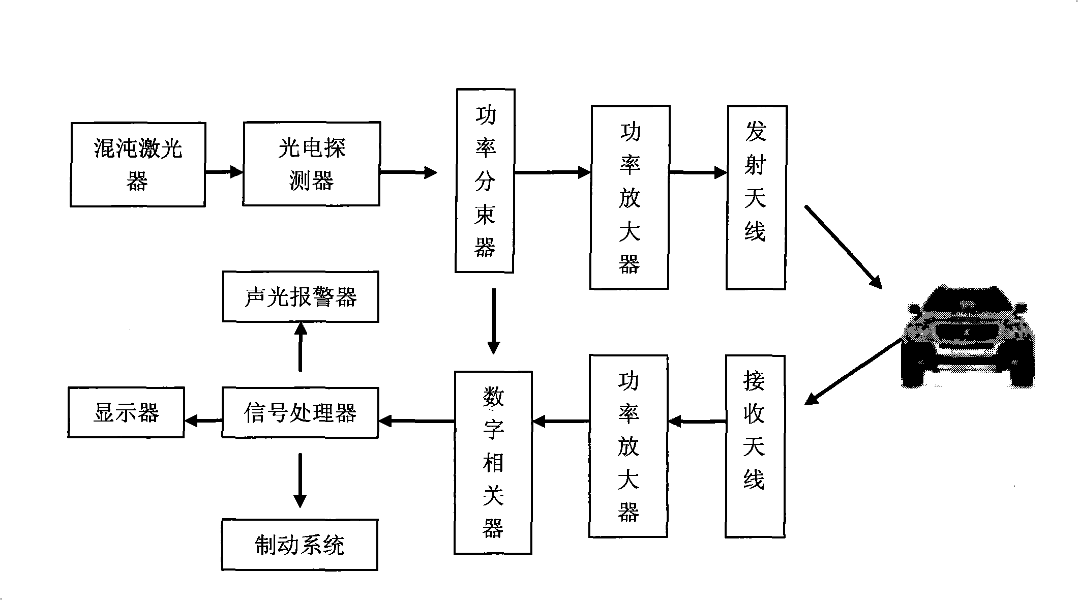
[0028] The chaotic laser utilizes the nonlinear characteristics of the semiconductor laser to generate chaotic laser, which is the key innovation of the present invention, and its specific implementation is shown in the chaotic laser implementation below.

[0029] The photodetector can use a high-speed / high-gain avalanche diode, such as the AD230-8 (T052S1) of Shanghai Perez Technology and Trade Co., Ltd., the cut-off frequency of this product is 2GHz, and the gain is 200.

[0030] The power splitter is a power splitter with single input and dual output, and there are many optional products on the market. For example, the XKG-2 one-to-two power beam splitter of Nanjing Wanquan Information Co., Ltd., the working frequency range of the power beam splitter is 0.8GHz-2.5GHz.

[0031] The transmitting antenna and the receiving antenna can be in the form of a horn-mouth antenna, and the double-ridge horn antenna HD-0220DRHA of Xi'an Hengda Microwave Technology Development Co., Ltd. ...

Embodiment approach 1

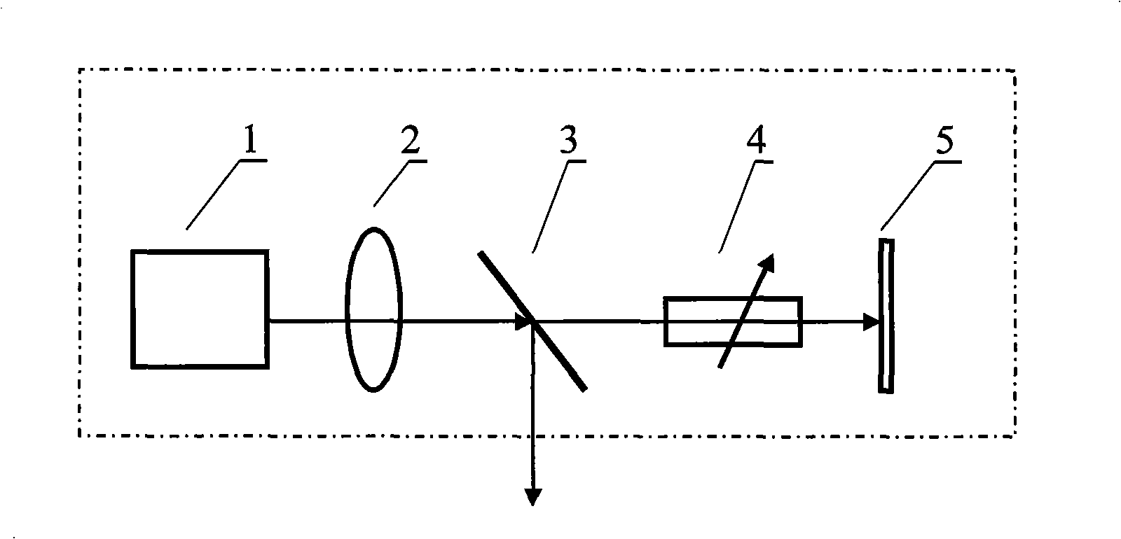
[0037] figure 2 It is a structural schematic diagram of a chaotic laser that uses optical feedback to realize chaotic laser output.

[0038] The chaotic laser includes a laser I1, a collimator lens 2, a beam splitter 3, an optical attenuator 4 and a mirror 5, and they are sequentially connected by light.

[0039] Laser I 1 is a semiconductor laser output from a commercial window. The output center wavelength is 808nm laser. A light attenuator 4 is reflected back to the laser I 1 by a reflective mirror 5 with a reflectivity of 85% to generate chaotic laser light. The reflected light of the beam splitter 3 is used as the output of the chaotic optical device.

Embodiment approach 2

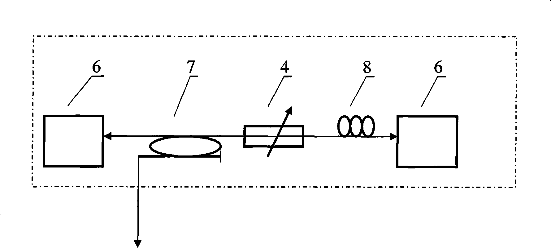
[0041] image 3 It is a structural schematic diagram of a chaotic laser that uses light injection to realize chaotic laser output.

[0042] The chaotic laser includes an injection laser II 6, a fiber coupler 7, an optical attenuator 4, a polarization controller 8 and an injected laser 6, and they are sequentially connected by optical fibers.

[0043] Laser II 6 is a semiconductor laser (LDM5S752) with commercial optical fiber output, the output center wavelength is 1550nm, and the output light enters into laser II 6 through fiber coupler 7, optical attenuator 4 and polarization controller 8 in sequence. The chaotic laser generated by the injection laser II 6 is output from one end of the fiber coupler 7 .


PUM


Abstract

The invention discloses an anti-collision system of a chaotic signal radar vehicle and a method thereof, and is characterized in that the chaotic signal produced by a chaotic laser in the system is used as a radar carrier signal; after passing a power splitter, one part of the radar carrier signal is used as a transmit; another part of the radar carrier signal is used as a reference signal; in the method, an echo signal and the reference signal in a correlation method are adopted to obtain the delay time of the echo signal so as to calculate and obtain the distance of a target obstacle; by using a distance difference in a certain time interval, the relative speed of the target obstacle is calculated and obtained. The anti-collision system disclosed by the invention utilizes the nonlinear characteristic of the radar to produce the chaotic signal as the carrier wave of the radar so as to obtain a broadband chaotic signal, thereby improving the anti-interference ability of the on-board radar, accurately realizing a corresponding warning and a braking, and avoiding the occurrence of an accident; besides, the anti-collision system has the advantages of simple structure, stable property and low price, thereby being applicable to various vehicles.

Description

technical field [0001] The invention relates to a radar automobile anti-collision system and method, in particular to a system and method for realizing automobile anti-collision by using a chaotic signal radar system. Background technique [0002] Today, with the increasingly developed road traffic, cars have become one of the important means of transportation for people, and driving safety has become a common concern of people. pregnancy. Since 1971, there have been various active vehicle collision avoidance radar systems and methods such as ultrasonic, laser, and microwave. Ultrasonic radar system is mainly used for automotive rear-view radar due to its poor target identification ability and short measurement distance. Lidar systems are greatly affected by atmospheric conditions, such as rain, fog, and dust, and are difficult to use in automotive collision avoidance systems. In comparison, the microwave automotive anti-collision radar system is the most widely used. ...

Claims


Application Information

Patent Timeline
Patent Type & Authority Applications(China)
IPC IPC(8): G01S13/93G01S13/02G01S7/02G01S7/28
Inventor 王云才龚天安王冰洁
Owner TAIYUAN UNIV OF TECH
Learn More