Servo engaging and disengaging gear and its operation mode

A clutch device and operating mode technology, applied in the field of transmission, can solve the problems of high cost, high transmission torque efficiency, small size, etc., and achieve excellent durability and reliability, rapid response, and low heat generation.

Active Publication Date: 2009-01-14
上海星之辰电气传动技术有限公司 +1
View PDF0 Cites 17 Cited by
  • Summary
  • Abstract
  • Description
  • Claims
  • Application Information

AI Technical Summary

Problems solved by technology

The friction and heat between the friction plates of this kind of clutch are serious, and the wear is also serious, so the friction clutch is a vulnerable part.
In addition, the quantitative control of the torque transmitted by the friction clutch is very difficult, and the mechanical structure of the manipulation control is also relatively complicated.
Hydraulic clutches use liquid as the transmission medium, and generally include input shafts, speed-increasing gear trains, working fluid flow chambers, impellers, driven wheels, etc. Although they can realize the functions of clutches, they cannot precisely control the transmitted torque, and the structure is complex and costly. high
[0006] The above clutches can control the torque isolation of the master and slave parts, gradually engage and stably transmit torque, but the friction and heat generated during the engagement process cannot recover the remaining energy during the engagement process; although the magnetic powder clutch can adjust the size of the transmitted torque to a certain extent, and responds The speed reaches hundreds of milliseconds, but none of the current clutches can meet the requirements of precise, wide-range, and fast-response control of torque transmission, high efficiency, small size, and low energy consumption.

Method used


Image

  • Servo engaging and disengaging gear and its operation mode
  • Servo engaging and disengaging gear and its operation mode
  • Servo engaging and disengaging gear and its operation mode

Examples


Embodiment 1

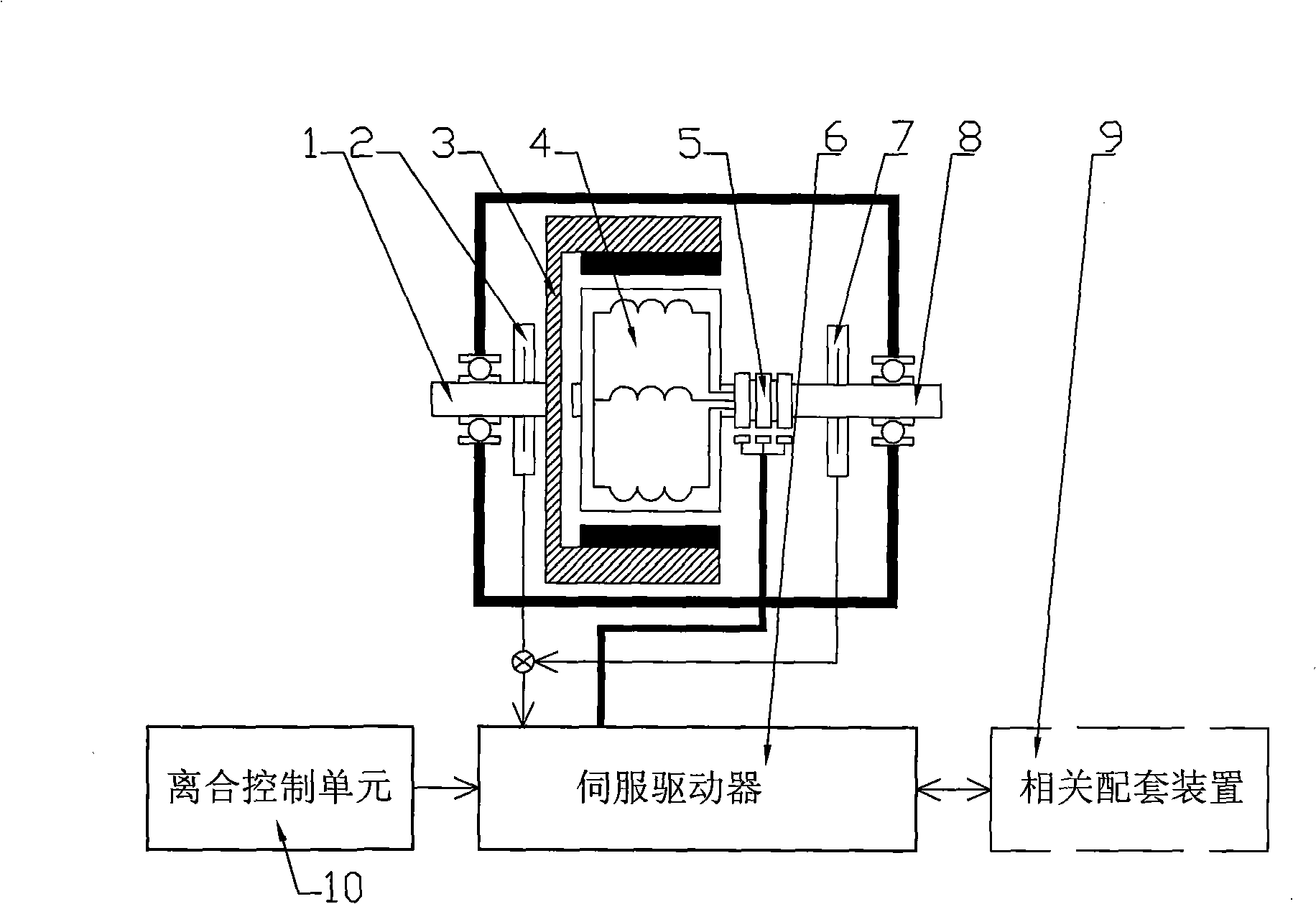
[0039] The structure of the embodiment 1 of the servo clutch device of the present invention is as follows: figure 1 As shown, the input shaft 1 is connected to the first rotor 3, the first rotor 3 is an outer rotor, embedded with permanent magnet poles, inside it is the second rotor 4, and the second rotor 4 is an inner rotor, which is wound on the iron core winding, the second rotor 4 is connected to the output shaft 8 of the device. The input shaft 1 and the output shaft 8 are on the same straight line. The first rotor 3 provides the second rotor 4 with a radial magnetic field. In this embodiment, the permanent magnet poles embedded in the first rotor 3 and the iron core and windings of the second rotor 4 constitute a permanent magnet synchronous motor, a switched reluctance motor, or a DC motor. A position sensor 2 is installed on the first rotor 3 . A B position sensor 7 is installed on the second rotor 4 shaft, and the A position sensor 2 and the B position sensor 7 a...

Embodiment 2

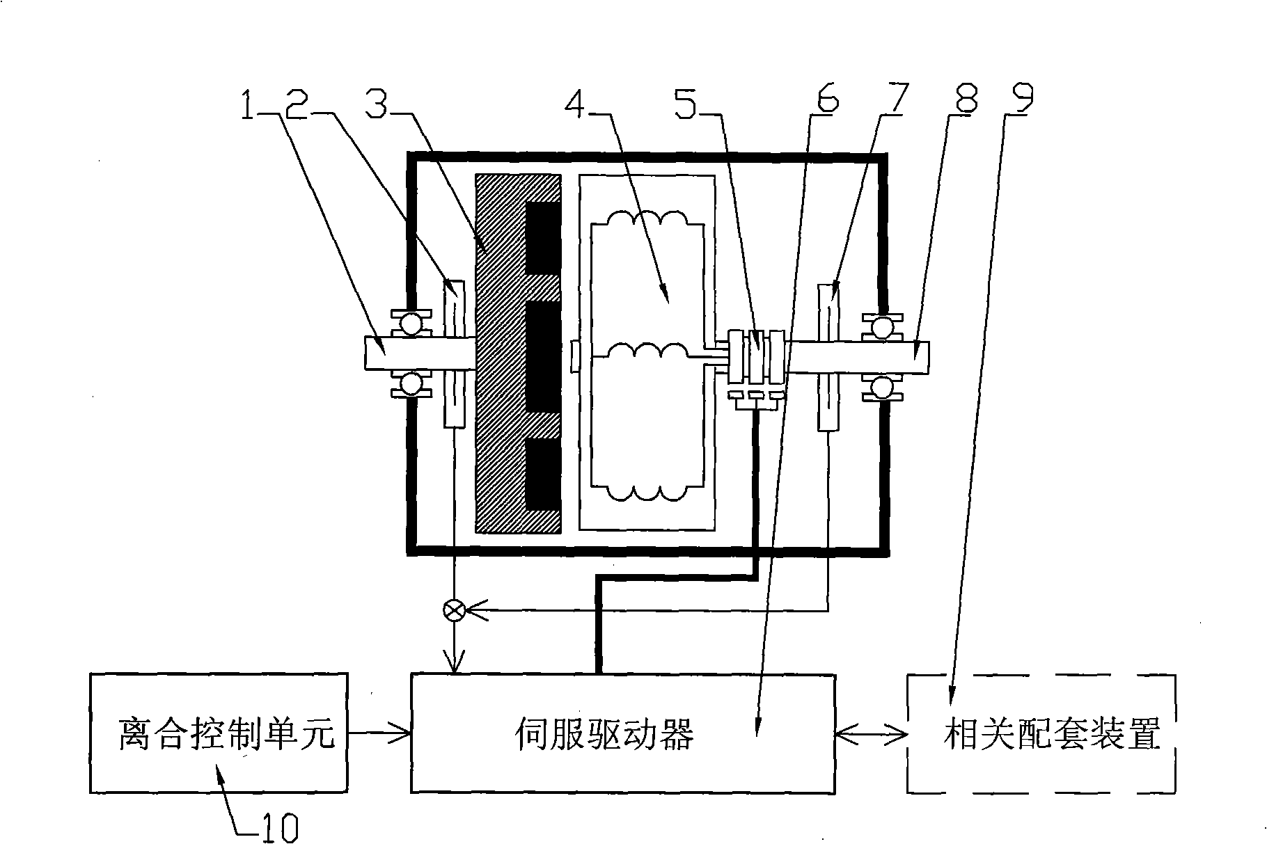
[0050] The structure of embodiment 2 of the servo clutch device of the present invention is as follows: figure 2 As shown, the first rotor 3 and the second rotor 4 are opposite to each other, maintaining an air gap, and the other structures are the same as those in Embodiment 1. The two form an axial magnetic circuit structure, and the direction of the air gap magnetic field between the two rotors is axial.

[0051] The operating mode of the embodiment 1 and 2 of the servo clutch device of the present invention is as follows: the servo driver 6 works in the torque servo mode, and the torque value of the master-slave part of the servo clutch linearly follows the torque setting value of the servo driver 6. During the process, the motions of the clutch input shaft 1 and output shaft 8 are determined by their respective synthetic torques, that is, by the electromagnetic torque of the servo clutch and the power torque or load torque on the two shafts 1 and 8 .

[0052] When the i...

Embodiment 3

[0066] The structure of embodiment 3 of the servo clutch device is mostly the same as that of embodiment 1 or 2, the difference is: the first rotor 3 is replaced with A position / speed sensor 2, and the second rotor 4 is replaced with B The position / speed sensor 7, the A position / speed sensor 2 and the B position / speed sensor 7 are connected to the servo driver 6 after the difference calculator, or the two position and speed sensors are connected to the servo driver 6 containing the difference calculator. The position and speed signals obtained by the two sensors 2 and 7 are sent to the servo driver 6 as the relative position and speed signals of the first and second rotors 3 and 4 after difference calculation; The servo driver of the / position servo unit, the servo driver 6 has a control port connected with the clutch control unit 10 for the speed / position setting signal and the torque limit signal, and works in a speed / position servo mode with a torque limit value.

[0067] I...


PUM


Abstract

The invention relates to a servo type clutch device and the operation mode thereof characterized in that two rotor shafts in line are respectively connected to an input shaft, a permanent magnetic pole is embedded on one of the two rotors or one of the two rotors is an exciting coil, the other rotor is a winding, the motor is formed by the winding and the permanent pole or the exciting coil, a servo drive is connected with the winding, a position / speed sensor of the servo drive is respectively arranged on the two rotor shafts, the servo drive has functions of torque servo and speed / position servo and a control port connected with a clutch control unit and receives the setting of torque or speed / position, mode switch signals and torque limiting setting signals. The servo drive is connected to a power storage device, and / or an electric device or the like. The operation mode is to confirm the work mode as required, the setting value of torque or speed / position and the torque limiting value are dynamically altered, thereby the clutch is controlled to operate in a master-slave isolation mode or in a gradually softly conjugation / separation mode or in a stable mode according to the given rule. The excess energy is converted into electric energy to use or store without radiation when the drive shaft speed is larger than that of the driven shaft.

Description

(1) Technical field [0001] The invention relates to the technical field of transmission, in particular to a servo clutch device and its operating mode. (2) Background technology [0002] Clutches are commonly used torque transmitting components in mechanical transmission systems. Common clutches include magnetic powder clutches, electromagnetic clutches, friction or hydraulic mechanical clutches, and the like. The main function is to isolate the torque transmission of the master and slave parts, realize the gradual engagement / disengagement of the master and slave parts, and transmit the working torque. [0003] The magnetic powder clutch adds magnetic powder between the master and slave parts, and the torque can be conveniently controlled by adjusting the excitation current of the slave part, and the torque has a certain linear relationship with the excitation current, and the excitation current has a wide range. Proportional. And the magnetic powder clutch has a relative...

Claims


Application Information

Patent Timeline
Patent Type & Authority Applications(China)
IPC IPC(8): H02K49/06H02P15/00
Inventor 吕虹
Owner 上海星之辰电气传动技术有限公司
Why Eureka
Try Eureka