Piezoelectricity type micro-pump and its driving circuit

A driving circuit, piezoelectric actuation technology, applied in circuits, piezoelectric devices/electrostrictive devices, piezoelectric/electrostrictive/magnetostrictive devices, etc. Electric actuation components actuation response time and other issues

Inactive Publication Date: 2009-01-14
MICRO BASE TECH CORP
View PDF2 Cites 6 Cited by
  • Summary
  • Abstract
  • Description
  • Claims
  • Application Information

AI Technical Summary

Problems solved by technology

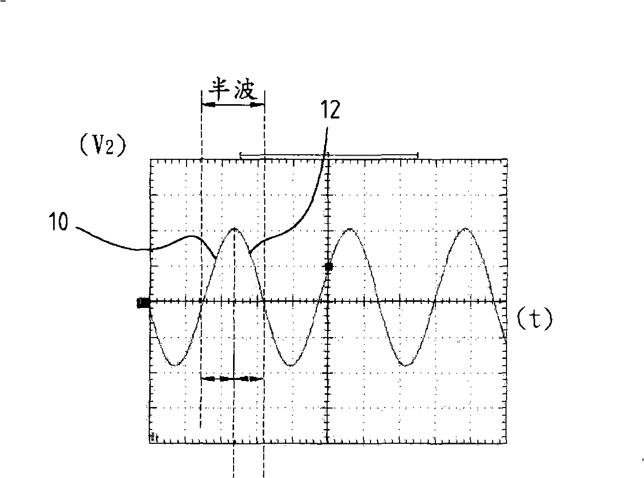
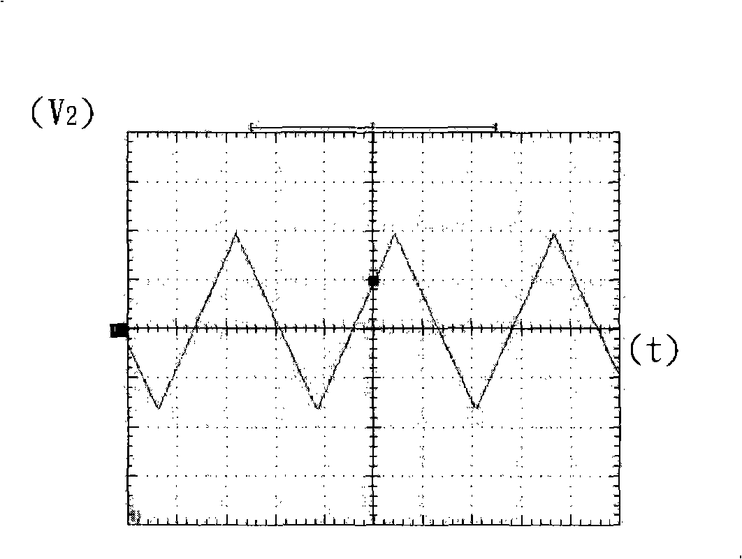
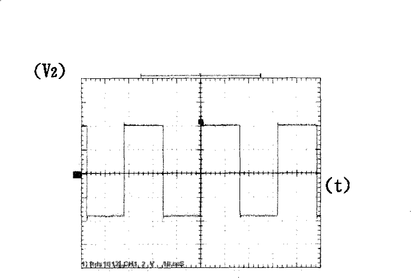
Observed Figure 1C and Figure 1D It is known from the half-wave front that the circuit will charge the piezoelectric actuator quickly. Although fast charging can make the piezoelectric actuator reach the top of the amplitude quickly, it also increases the power consumption.
In addition, due to the fast charging of the piezoelectric actuator, the piezoelectric actuator will resonate naturally when the piezoelectric actuator reaches the peak of its amplitude and before the piezoelectric actuator moves in the opposite direction. frequency creates vibration until the piezo actuator is discharged and act

Method used


Image

  • Piezoelectricity type micro-pump and its driving circuit
  • Piezoelectricity type micro-pump and its driving circuit
  • Piezoelectricity type micro-pump and its driving circuit

Examples


Embodiment Construction

[0035]FIG. 2A is a schematic cross-sectional view of a piezoelectric micro-pump with a driving circuit of the present invention. The piezoelectric micropump (2) can be used to transport a fluid, which includes all liquids and gases. Examples of liquids include: diesel, gasoline, methanol, ethanol, pure water, methanol aqueous solution, sea water and other liquids. Examples of gases include: gas, hydrogen, pure oxygen, air, carbon dioxide and other gases. As shown in Fig. 2A, the piezoelectric micro-pump (2) includes: a casing (20), a piezoelectric actuator component (22) and a drive circuit (3). First, the housing (20) has an internal chamber (200), an inlet (202) and an outlet (204), and in actual situations, the piezoelectric micro-pump (2) is usually provided with a valve assembly (not shown in the figure) ) at the entrance (202) and exit (204). The piezoelectric actuator component (22) is arranged in the inner chamber (200) and is used for compressing the space of the i...


PUM


Abstract

The invention relates to a drive circuit applying in a piezoelectric actuating component composed of a drive period generation unit and a switch circuit unit. The drive period generation unit also comprises a drive indexing signal and a programmed microcontroller, wherein the programmed microcontroller generates a programmed drive period signal corresponding to the drive indexing signal after receiving the drive indexing signal and responding to the drive indexing signal. The switch circuit unit generates an alternate drive voltage corresponding to the drive period signal after connecting to the drive period generation unit and the piezoelectric actuating component as well as receiving the drive period signal. The waveform of the half wave leading edge of the alternate drive voltage has a gravity curve shape, the waveform of the half wave trailing edge of the alternate drive voltage is close to a vertical shape and the alternate drive voltage is connected to the piezoelectric actuating component.

Description

technical field [0001] The present invention relates to a driving circuit, especially a driving circuit applied to a piezoelectric actuator assembly, and a piezoelectric (Piezoelectric) micro-pump with the driving circuit. Background technique [0002] Figure 1E It is a driving circuit of a traditional piezoelectric actuator, which is disclosed in Japanese Patent JP2004282988A. Figure 1E The driving circuit shown can only charge and discharge the electrode on one side of the piezoelectric actuator component (11), so the vibration amplitude of the piezoelectric actuator component (11) will only reach half of the level. Figure 1F It is another traditional piezoelectric actuator drive circuit disclosed in US Patent No. US20070046143A1. exist Figure 1E and Figure 1F Among them, the source of the driving signal is generated by the electrodes of the piezoelectric actuator components (11), (13), the purpose of which is to enable the piezoelectric material to vibrate at its ow...

Claims


Application Information

Patent Timeline
IPC IPC(8): H02N2/00H02N2/06H01L41/09H01L41/083F02M51/00
Inventor 孟宪铠谢淑品林建华许由忠林泰轩
Owner MICRO BASE TECH CORP
Why Eureka
Try Eureka