Internal and external fins intubatton type high temperature heat exchanger

A high-temperature heat exchanger and intubation type technology, which is applied in the field of inner and outer fin intubation type high-temperature heat exchangers, can solve the problems of limited expansion and contraction capacity of corrugated expansion joints, limited use pressure on the shell side, and large material consumption. Improve heat exchange efficiency and compactness, save high temperature resistant materials, and increase the effect of heat exchange area

Inactive Publication Date: 2009-01-21
XI AN JIAOTONG UNIV
View PDF0 Cites 16 Cited by
  • Summary
  • Abstract
  • Description
  • Claims
  • Application Information

AI Technical Summary

Problems solved by technology

[0003] There are many problems in the traditional shell-and-tube heat exchanger: ①The internal temperature gradient of the high-temperature heat exchanger is relatively large, while the tube sheets at both ends of the traditional fixed-tube-sheet heat exchanger are fixed on the shell, and the heat exchange tubes are fixed on the tubes at both ends. The thermal stress on the heat exchange tubes and tube sheets is very significant. Generally, corrugated expansion joints are used on the shell side to compensate for thermal expansion, but the expansion and contraction capacity of corrugated expansion joints is limited, and the operating temperature is also limited. The mechanical strength under the condition is very low, and the heat exchanger cannot operate reliably for a long time under high temperature conditions; There is no thermal stress, but the floating head heat exchanger is heavy, the material consumption is large, and the cost is high, and because the floating head cover and the flange have a considerable area, the result is that the diameter of the shell is increased, and part of the fluid flows from the tube bundle to the shell. The annular channel between them is bypassed and does not participate in heat exchange, which reduces the heat exchange efficiency, and at the same time, the operating pressure of the shell side is limited; ③The traditional U-shaped tube heat exchanger only needs one tube plate, and the tube bundle can be freely expanded and contracted without generating heat. Stress, but the curved tube needs a certain bending radius, so it is necessary to use different curvature molds to bend the tube during manufacture, and the effective utilization rate of the tube sheet is reduced, the structure is not compact, and the central part of the U-shaped tube bundle has a great impact on heat exchange. device operation has an adverse effect on the
[0004] Many scholars at home and abroad have proposed to apply the intubated heat exchange tube structure to high-temperature heat exchangers. The heat exchange tube of the intubated high-temperature heat exchanger has a free end, and the thermal expansion of the heat exchange tube is completely free without any restrictions. , satisfying the principle of thermal expansion freedom, avoiding the problem of thermal stress, very suitable for high-temperature environments, foreign countries have developed intubated high-temperature heat exchangers for fluidized bed, external combustion combined cycle and other environments, but the existing There are also some problems in the intubated high-temperature heat exchanger: ① The intubated heat exchange tubes of the existing intubated high-temperature heat exchangers generally use bare tubes, and no extended surfaces such as fins are added, resulting in the overall heat exchange of the heat exchanger. The thermal efficiency is not high; ②The high-temperature heat exchanger is required to be made of high-temperature-resistant materials, and the cost is very high. In fact, the high-temperature gas can be made of ordinary materials after being cooled to a lower temperature by heat exchange. According to statistics, the cost of the heat exchanger is in There will be a substantial increase above 675°C, and most designed high-temperature heat exchanger heat exchange tubes are made of only one high-temperature resistant material, resulting in waste of materials, and cost issues limit the application and promotion of high-temperature heat exchangers

Method used


Image

  • Internal and external fins intubatton type high temperature heat exchanger
  • Internal and external fins intubatton type high temperature heat exchanger
  • Internal and external fins intubatton type high temperature heat exchanger

Examples


Embodiment Construction

[0039] Accompanying drawing is the specific embodiment of the present invention.

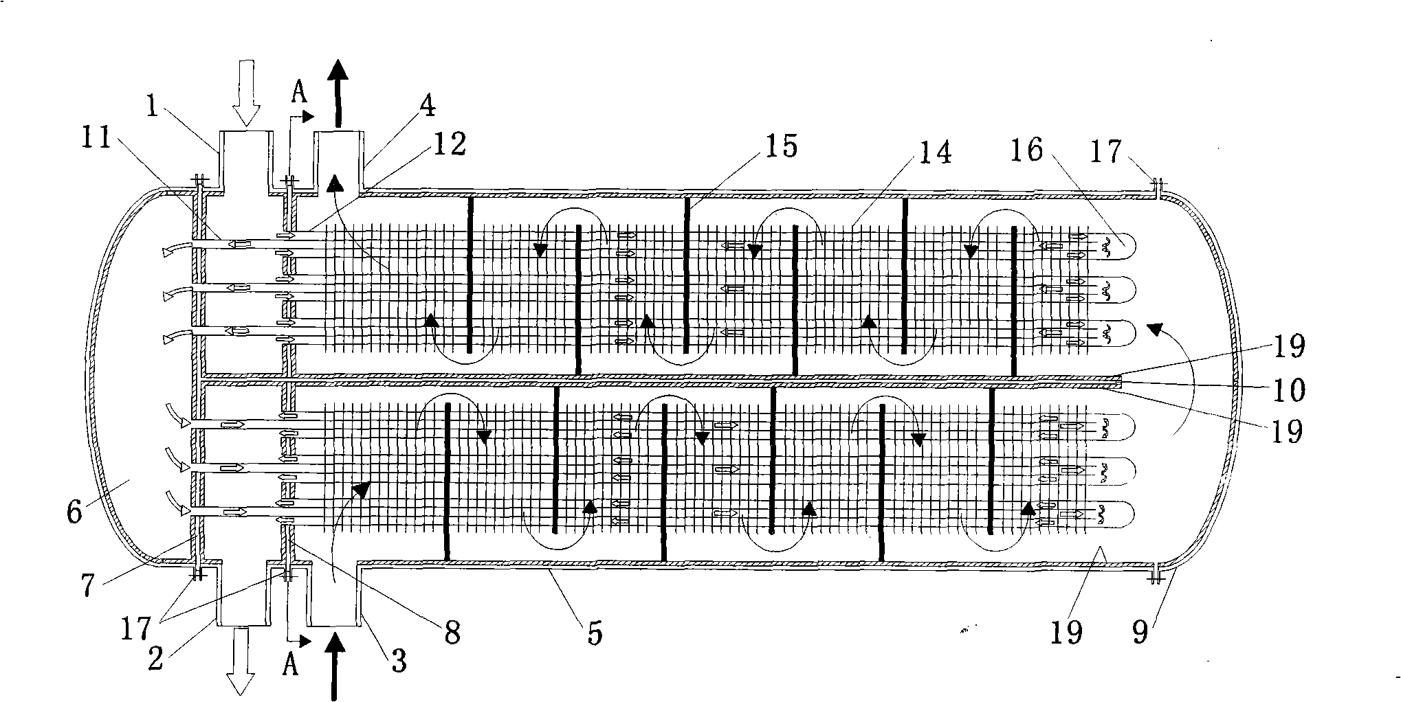
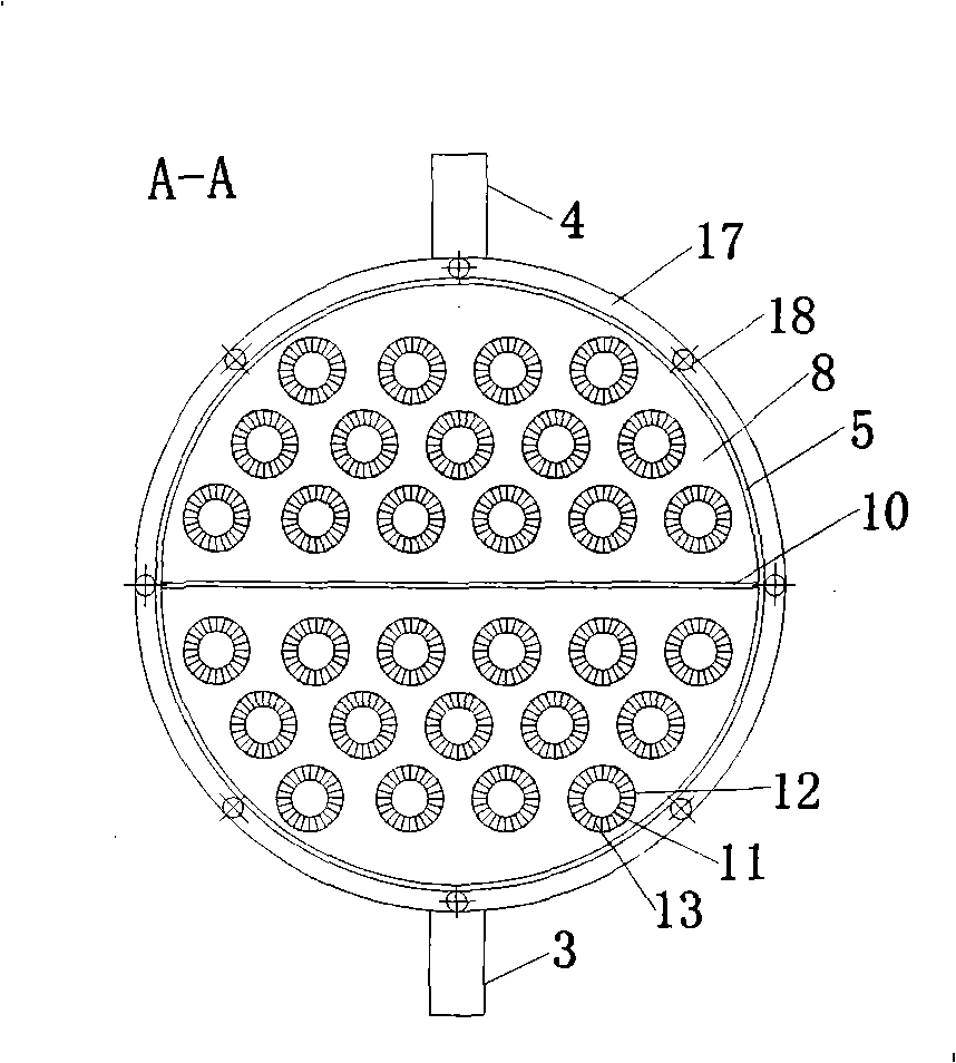
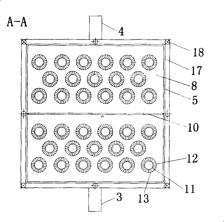
[0040] Referring to Fig. 1 (a), the inner and outer fin tube type high temperature heat exchanger of the present invention includes a shell 5, a tube box 6 at the front end of the shell 5 and a head 9 at the rear end, and the shell 5 forms Longitudinal partitions 10 and baffles 15 are arranged on the shell side, the inner tube sheet 7 and the outer tube sheet 8 are arranged on the end of the shell 5, and the tube side inlet is arranged between the inner tube sheet 7 and the outer tube sheet 8 Tube 1, tube-side outlet tube 2, shell-side inlet tube 3 and shell-side outlet tube 4 are arranged on the shell 5 behind the outer tube tube plate 8. The inner tube 11 is arranged in parallel on the inner tube tube sheet 7, and the outer tube 12 is arranged in parallel on the outer tube tube sheet 8. Both the inner tube 11 and the outer tube 12 have a free end. The inner tube 11 is a diversion tube with op...


PUM


Abstract

The invention relates to an internal and external fin bayonet-tube type high temperature exchanger, which comprises a casing, a tube box which is connected on the casing, a closed head, a longitudinal baffle, a baffle plate, tube plates of an internal tube and an external tube, a tube side inlet and outlet pipe, a casing side inlet and outlet pipe, wherein one ends of the internal tube and the external tube are respectively fixed on the tube plates of the internal tube and the external tube, and the other ends are both free ends, the internal tube is a honeycomb duct whose two ends are open, and the external tube is a heat exchange tube whose one end is open, and the other end is closed, the internal and external walls of the external tube are respectively provided with an internal fin and an external fin to form an internal and external fin bayonet-tube heat exchanging unit, and the internal fin can relatively move to the internal tube. The exchanger is divided into a high temperature shell pass and a low temperature shell pass, the components of the two shell passes are respectively produced by high temperature-resistant material and common material, also can be produced by the same material. The internal walls of the casing, the longitudinal baffle and the tube plates of the internal tube and the external tube are provided with ceramic insulating layers, and fluid on two sides of a shell is crossly flow in reverse directions. The invention can increase the heat exchange efficiency and compactness of the exchanger, reduces production cost, and can overcome the thermal stress problem, and can be applied in high temperature condition.

Description

technical field [0001] The invention relates to a shell-and-tube heat exchanger, in particular to an inner and outer fin tube-type high-temperature heat exchanger used in industries such as chemical industry, metallurgy, glass manufacturing and garbage incineration. Background technique [0002] High-temperature heat exchangers generally refer to heat exchange equipment with a medium temperature above 600°C. In recent years, high-temperature heat exchangers have developed in the direction of high temperature and high pressure, such as ethylene cracking process, hydrogen cyanide synthesis, solid oxide fuel cells and other industries. The operating temperature of the heat exchanger used is often higher than 1000°C, which poses a great challenge to the performance of the heat exchanger. [0003] There are many problems in the traditional shell-and-tube heat exchanger: ①The internal temperature gradient of the high-temperature heat exchanger is relatively large, while the tube s...

Claims


Application Information

Patent Timeline
Patent Type & Authority Applications(China)
IPC IPC(8): F28D7/12
Inventor 王秋旺马挺陈秋炀
Owner XI AN JIAOTONG UNIV
Why Eureka
Try Eureka