
Direct-action power generation system with speedup spring forced vibration

A technology of power generation system and forced vibration, which is applied in the direction of electromechanical devices, electrical components, electric components, etc., can solve the problems of fixed frequency and narrow working dynamic range of the engine, and achieve the reduction of coil weight, increase of volume capacity, and increase of coil intensity effect

Inactive Publication Date: 2009-01-28
TIANJIN CHANGING POWER TECH
View PDF2 Cites 10 Cited by
  • Summary
  • Abstract
  • Description
  • Claims
  • Application Information

AI Technical Summary

Problems solved by technology

[0004] In the 200710004101.6 invention, the "forced vibration direct power generation, buffer energy storage, and electric drive vehicle" proposed in the direct power generation scheme adjusts the power by controlling the number of working cylinders and the distance of the intake stroke. The main disadvantage is that the frequency is relatively Fixed, engine operating dynamic range is narrow

Method used


Image

  • Direct-action power generation system with speedup spring forced vibration
  • Direct-action power generation system with speedup spring forced vibration
  • Direct-action power generation system with speedup spring forced vibration

Examples


Embodiment Construction

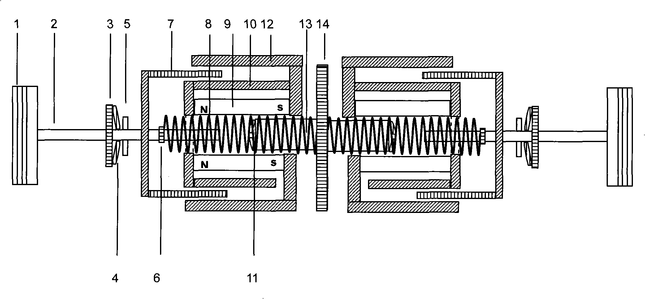
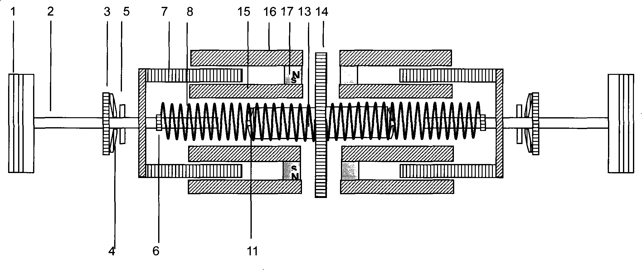
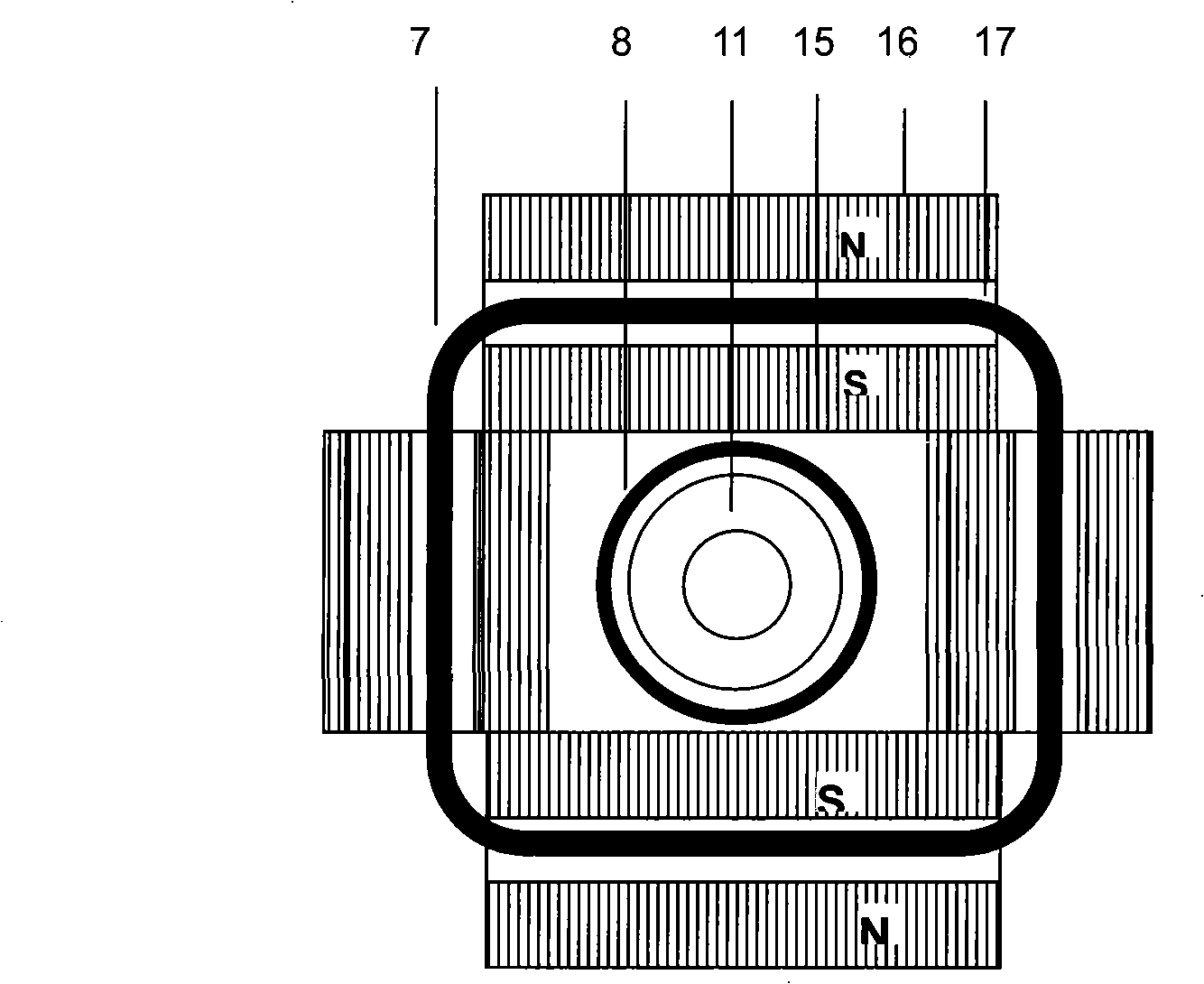
[0022] exist figure 1 Among them, the piston (1) is connected with the connecting rod (2), the force plate (5), the generator coil (7), the coil spring seat (6), and the coil spring (8), and the other end of the coil spring (8) is connected with the spring seat (14) connection, the disc spring (4) is connected with the spring seat (3), the spring seat (3) is fixed on the body, the central opening is slidably connected with the connecting rod (2), the disc spring (11) is connected with the disc spring The spring seat (13) is connected, and the disc spring seat (13) is designed as a column, mainly in order to reduce the length of the connecting rod and reduce the weight of the system. The permanent magnet (9) is hollow and is connected with the body axially. 10) and (12) form a magnetic field perpendicular to the axial direction, the reciprocating motion of the piston (1) drives the generator coil (7) to reciprocate in the magnetic field, and the balance position of the piston i...


PUM


Abstract

The invention discloses a directly operated power generation system which directly utilizes the rectilinear motion of a reciprocating engine piston to drive coils or a magnet to generate electric current for power generation. During the period of non-expansion stroke, the motion of the piston is driven by utilizing a vibrating system and the electromagnetic force of the coils; in the system, the piston, power generation coils and a linking mechanism are connected with a coil spring. The piston and the coils connected with the piston are controlled by a balancing spring at the near end of the piston and an accelerating spring at the remote end of the piston by a stress board and a connecting rod and then a forced vibration system is formed. The system uses a method for adjusting the movement velocity of the piston in the last phase of the expansion stroke so as to realize the adjustment of the system frequency and also uses a method for adjusting the number of working cylinders and the air input capacity to carry out the power regulation; by utilizing that the system is characterized by no fixed top dead center and the easily adjustable compression ratio, a compression-ignition type ignition is adopted and the volume compression ratio can be adjusted according to the air inlet capacity so as to realize the comparatively high compression ratio within a wide working range, thereby improving the efficiency.

Description

technical field [0001] The invention relates to a direct-motion power generation system, in particular to a forced-vibration direct-motion power generation system for an electric drive vehicle. Background technique [0002] Currently known technologies for improving automobile efficiency (1) automobile injection technology, which improves efficiency by precisely controlling the amount of oil; (2) lean burn technology, which increases compression ratio and improves efficiency through stratified olefin combustion, high-pressure ignition and other technologies; (4) Variable compression ratio, through mechanical devices, increases the compression ratio at low power demand and improves efficiency; (5) hybrid electric vehicles, by making the engine mainly run in the middle and high efficiency range to improve fuel efficiency, using power generation and Stored in the battery, the battery and the motor provide the driving force when the power demand is low, and the engine or the eng...

Claims


Application Information

Patent Timeline
IPC IPC(8): F02B63/04F02D17/00F02D13/02F02D15/04H02K7/18H02K35/04
CPCY02T10/18
Inventor 唐明龙
Owner TIANJIN CHANGING POWER TECH
Learn More