
Method for preparing nano CMOS integrated circuit by micro process
An integrated circuit, micron-scale technology, applied in the manufacturing of circuits, electrical components, semiconductor/solid-state devices, etc., can solve the problems of rising production costs, restricting the development of the semiconductor industry, waste of resources and energy, etc., to improve manufacturing capacity and achieve leapfrogging development, the effect of small conduction channel
- Summary
- Abstract
- Description
- Claims
- Application Information
AI Technical Summary
Problems solved by technology
Method used
Image

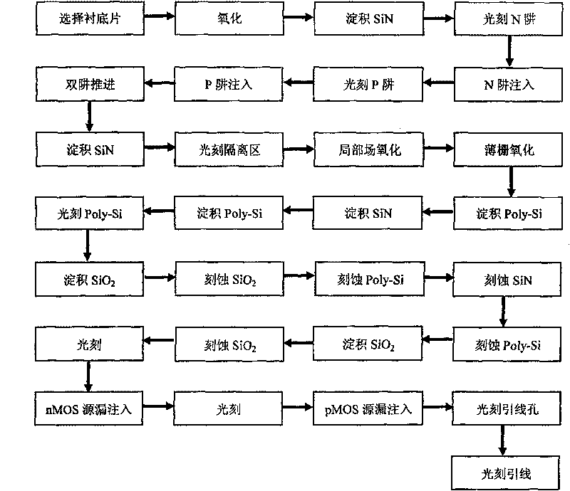
Examples
Embodiment 1
[0030] Embodiment 1: prepare the CMOS integrated circuit that conduction channel is 45nm on Si substrate, concrete steps are as follows:
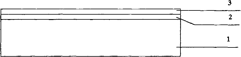
[0031] Step 1, deposit a masking layer, such as figure 2 (a) shown.
[0032] (1a) Select the crystal orientation as and the doping concentration as 10 15 cm -3 Left and right p-type Si substrate sheets 1;
[0033] (1b) Thermally oxidize a layer of SiO with a thickness of 20 nm on the substrate 2 buffer layer 2;
[0034] (1c) on SiO 2 A 100nm-thick SiN layer 3 is deposited on the buffer layer by low-pressure chemical vapor deposition (LPCVD) for masking of well implantation.
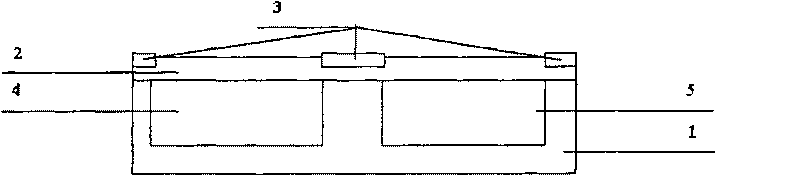
[0035] Step 2, forming a well region, such as figure 2 (b) shown.
[0036] (2a) Photoetching the P well region 4 and the N well region 5 on the SiN layer 3 according to the phase sequence;
[0037] (2b) Boron is implanted in the P well region to form a p-type region, and SiO is thermally oxidized on the surface of the P well region 2 , while advancing the ...
Embodiment 2
[0066] Embodiment 2: prepare the CMOS integrated circuit that conduction channel is 65nm on SOI substrate, concrete steps are as follows:
[0067] Step 1, deposit a masking layer, such as figure 2 (a) shown.
[0068] (1a) Select the crystal orientation as and the doping concentration as 10 15 cm -3 left and right p-type SOI substrates 1;
[0069] (1b) Thermally oxidize a layer of SiO with a thickness of 40 nm on the substrate 2 buffer layer 2;
[0070] (1c) on SiO 2 A 150nm-thick SiN layer 3 is deposited on the buffer layer by means of APCVD for the masking of the implantation in the well region.
[0071] Step 2, forming a well region, such as figure 2 (b) shown.
[0072] (2a) Photoetching the P well region 4 and the N well region 5 on the SiN layer 3 according to the phase sequence;
[0073] (2b) Boron is implanted in the P well region to form a p-type region, and SiO is thermally oxidized on the surface of the P well region 2 , while advancing the P well, formin...
Embodiment 3
[0102] Embodiment 3: prepare the CMOS integrated circuit that conduction channel is 90nm on Si substrate, concrete steps are as follows:
[0103] Step 1, deposit a masking layer, such as figure 2 (a) shown.
[0104] (1a) Select the crystal orientation as and the doping concentration as 10 15 cm -3 Left and right p-type Si substrate sheets 1;
[0105] (1b) Thermally oxidize a layer of SiO with a thickness of 60 nm on the substrate 2 buffer layer 2;
[0106] (1c) on SiO 2 A 200nm thick SiN layer 3 is deposited on the buffer layer by plasma-enhanced chemical vapor deposition (PECVD) for the masking of well implantation.
[0107] Step 2, forming a well region, such as figure 2 (b) shown.
[0108] (2a) Photoetching the P well region 4 and the N well region 5 on the SiN layer 3 according to the phase sequence;
[0109] (2b) Boron is implanted in the P well region to form a p-type region, and SiO is thermally oxidized on the surface of the P well region 2 , while advanci...
PUM
 Abstract
Description
Claims
Application Information