Desulfurization dust removing method of industrial furnace

A technology for desulfurization and dust removal, industrial furnaces and kilns, which is applied in the direction of separation methods, chemical instruments and methods, and separation of dispersed particles. It can solve the problems of high power consumption, large investment in dust collectors, and large investment, and achieve long contact time and high dust removal efficiency. high effect

Inactive Publication Date: 2009-02-11
姚立猛
View PDF0 Cites 12 Cited by
  • Summary
  • Abstract
  • Description
  • Claims
  • Application Information

AI Technical Summary

Problems solved by technology

This type of method can remove harmful particles in the cupola flue gas and eliminate some harmful gases in the flue gas, but this type of dust collector has a large investment, high power consumption, and high operating costs
[0007] In summary, the

Method used


Image

  • Desulfurization dust removing method of industrial furnace
  • Desulfurization dust removing method of industrial furnace
  • Desulfurization dust removing method of industrial furnace

Examples


Embodiment 1

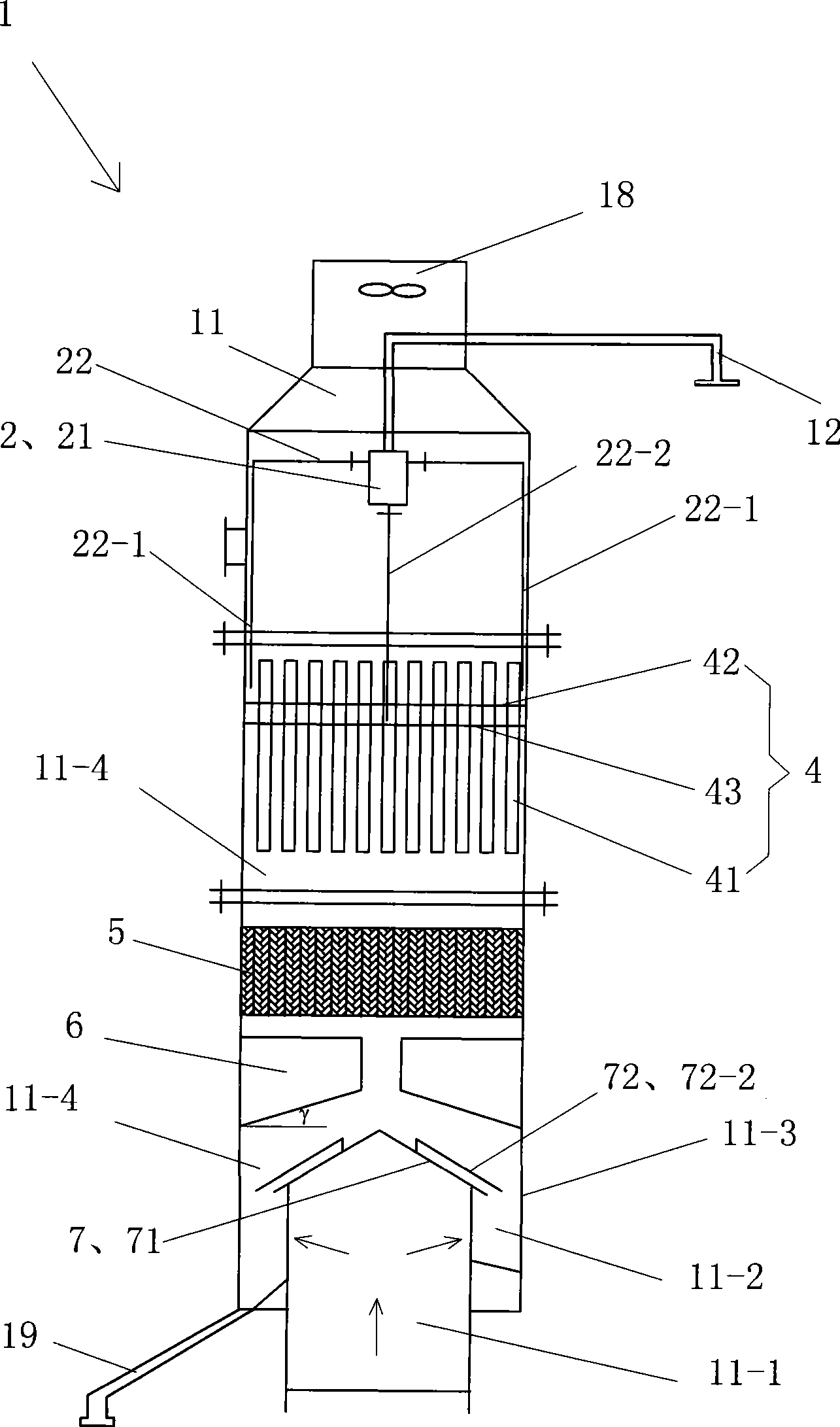
[0044] See figure 1 , the industrial kiln desulfurization and dedusting method of the present embodiment has the following steps:

[0045] ① Connect the flue gas inlet of the industrial furnace desulfurization and dust removal device 1 with the flue gas outlet of the industrial furnace. Sewage pipe 19, exhaust fan 18, water flow distributor 2, contact cooling spray device 4 and blocking cap 7.

[0046] The exhaust fan 18 is located in the housing 11 and at the upper opening of the housing 11, so that when the internal resistance needs to be reduced, the exhaust fan 18 can be activated to make the flue gas flow smoothly and not be blocked.

[0047] The housing 11 has a diameter of 2.6 m. The housing 11 has a flue gas inlet 11-1, an annular bottom plate 11-2 and an annular side plate 11-3, the flue gas inlet 11-1 is located in the center of the annular bottom plate 11-2, the annular bottom plate 11-2 and the annular side plate 11- 3 are airtightly connected together and locat...

Embodiment 2

[0057] still see figure 1 as well as Figure 4 , the method of the present embodiment is the same as embodiment 1, the difference is:

[0058] The desulfurization dust collector 1 in step ① also includes 18 swirl guide plates 6 arranged in the spray area 11 - 4 and above the blocking cap 7 . The shape of each swirl deflector plate 6 is the same, being a quadrangular plate, its upper edge is horizontal, its inner edge and outer edge all form a 90° angle with the upper edge, and the length of the outer edge is greater than the length of the inner edge , so that the lower edge is inclined with a high inside and a low outside, and the inclination angle γ is 25°. The plate body of each swirl flow guide plate 6 is welded and fixed on the annular side plate 11-3 of the housing 11 by its outer edge, and they are located at the same height position. On the same height, the plate body of each swirl guide plate 6 is at an angle of 10° to the diameter direction of the housing 11 passin...

Embodiment 3

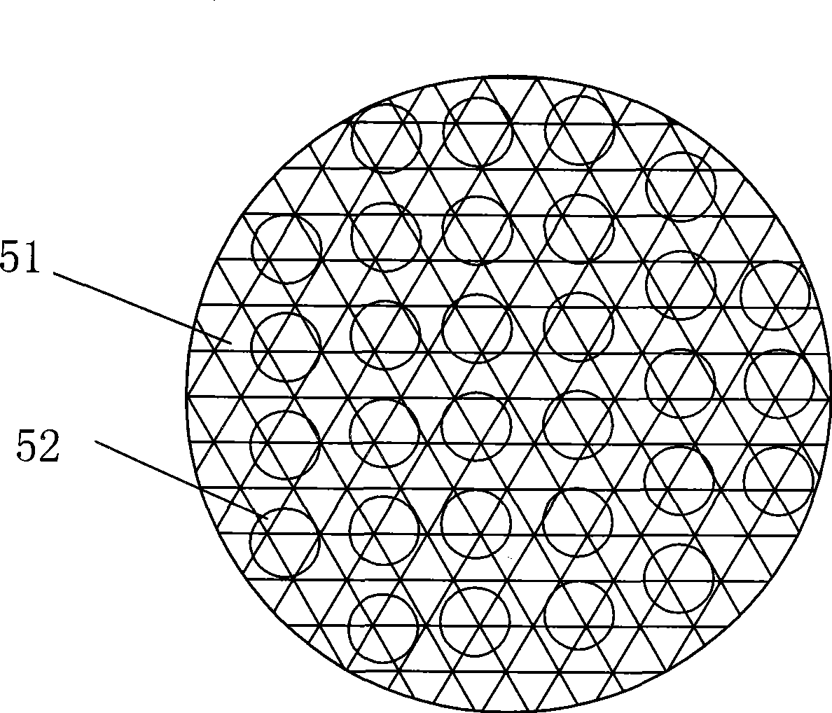
[0062] still see figure 1 as well as image 3 , the rest of the method of the present embodiment are the same as in embodiment 1, the difference is:

[0063]The desulfurization and dust removal device 1 in step ① also includes a scale mesh atomization device 5 . The scale mesh atomization device 5 is arranged in the spray area 11 - 4 and is located between the contact cooling spray device 4 and the swirl guide plate 6 . The scale-mesh atomization device 5 includes a mesh bottom plate 51 and each atomizing cylinder 52 is vertically parallel and closely arranged on the mesh bottom plate 51 . Each atomizing tube is made of steel rhombus perforated plate wound into a cylindrical shape.

[0064] In step ②, the cooling water that falls into the spray area from the contact cooling spray device 4 in a spray shape first falls on the scale mesh atomization device 5, and then falls from the scale mesh atomization device 5, wherein the cooling water Most of it falls on the swirl guide...


PUM


Abstract

The invention discloses a desulfurization and dust removal method for an industrial furnace, which comprises the followings steps: 1. a flue gas inlet of a desulfurization and dust removal device of the industrial furnace is communicated with a flue gas outlet of the industrial furnace; 2. cooling water is pumped into a water inlet pipe, enters a contact type cooling spraying device through a flow partitioning device, falls into a spraying area in spraying shape and then is discharged along a blowdown pipe; 3. flue gas generated from the industrial furnace enters the desulfurization and dust removal device of the industrial furnace from bottom to top from the flue gas inlet of a shell, is contacted with cooling water between a barrier cap and an annular bottom plate firstly and then with the cooling water in the spraying shape and falling down from the contact type cooling spraying device to carry out heat exchange; 4. after the heat exchange, phase change is carried out to steam so as to cause the steam to turn into liquid water drops, during the phase change, adjacent sulfur dioxide is absorbed by the water drops and adjacent minimal dust grains are adsorbed by the water drops effectively. The desulfurization and dust removal method for the industrial furnace has good dust removal effect, high desulfurization efficiency, as well as low energy consumption, low equipment investment and low operation cost.

Description

technical field [0001] The invention belongs to the technical field of atmospheric environment protection, and in particular relates to an industrial kiln desulfurization and dust removal method. Background technique [0002] The combustion products of industrial furnaces have caused serious pollution to the atmosphere, affecting human survival and quality of life. For example, the sulfur in the fuel of industrial furnaces has formed acid rain in the atmosphere, resulting in reduced agricultural production. The harmful fine dust emitted by industrial furnaces has affected human beings. health and pollute the environment. Therefore, countries all over the world have stricter and stricter restrictions on the emission of various industrial furnaces, and have established emission standards for industrial furnaces and kilns. [0003] The desulfurization and dust removal methods of industrial furnaces are mainly divided into three categories. One is dry dust removal. collection,...

Claims


Application Information

Patent Timeline
IPC IPC(8): B01D53/18B01D53/78B01D53/50B01D47/06
Inventor 姚立猛
Owner 姚立猛
Why Eureka
Try Eureka