
Laser-arc composite heat-source narrow-gap precision welding method

A compound heat source and precision welding technology, applied in laser welding equipment, welding equipment, manufacturing tools, etc., can solve problems such as difficult precision welding, lower laser welding efficiency, large arc geometry, etc., to achieve high-quality welding, welding effect and Obvious effect

Inactive Publication Date: 2009-02-11
HARBIN WELDING INST LTD
View PDF1 Cites 41 Cited by
  • Summary
  • Abstract
  • Description
  • Claims
  • Application Information

AI Technical Summary

Problems solved by technology

However, preheating and post-heat treatment will complicate the welding process and reduce the efficiency of laser welding. For some materials with a high hardening tendency, even if preheating and post-heating are adopted without filler metal Heat treatment cannot avoid the generation of cracks. Generally speaking, laser welding is usually used instead of laser welding for the welding of materials with a large hardening tendency.
By selecting the appropriate filler metal, laser filler wire welding can better improve the structure of the weld metal and prevent welding cracks, but laser filler wire welding also has some disadvantages
Since a large part of the laser energy in the welding process is used to melt the filler metal, laser wire filler welding will seriously affect the penetration ability of the laser and the welding speed, especially in the case of greater requirements for weld penetration. The weld penetration requires and guarantees the fusion of the weld, and a larger groove needs to be opened, which will further reduce the welding efficiency and cause greater welding deformation
[0003] Application No. 200610007614.8 Invention Patent "A method for connecting dissimilar metals with a large-spot laser and arc composite heat source" proposes a composite heat source composed of laser and arc. This composite heat source is difficult to use due to factors such as large arc power and arc geometry. Precision welding in narrow gaps

Method used


Image

  • Laser-arc composite heat-source narrow-gap precision welding method

Examples


Embodiment Construction

[0022] best practice

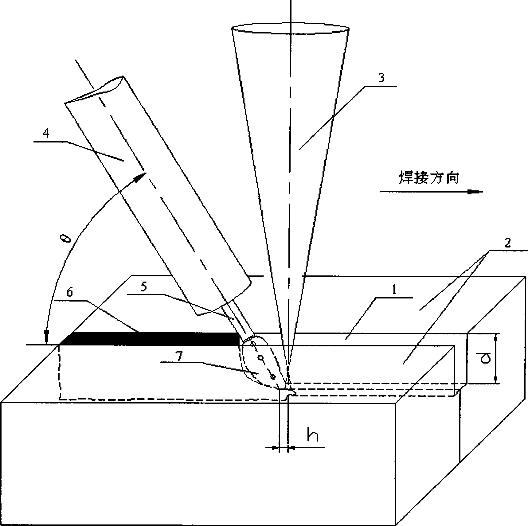
[0023] The laser used in the test is the HL2006D Nd:YAG solid-state laser produced by the German HAAS company, with a maximum output power of 2.6KW and a continuous laser wave with an output wavelength of 1.06μm, and a focusing lens with a focal length of 200mm; the arc welding machine is produced by the Austrian F0NIUS company TPS5000 digital GMA welding power supply and wire feeder; the test materials used are 38CrMoAlA nitriding steel and 1Cr17Ni2 martensitic stainless steel, and the size of the test plate is 200mm×40mm×8mm; the diameter developed by Harbin Welding Research Institute is Φ1. 0mm 309 stainless steel wire. The test plate adopts the narrow gap formed by "I" and rectangular groove respectively. The groove size is 0.8mm in width and 3.0mm in depth and 0.8mm in width and 3.5mm in depth. Preset solder.

[0024] The specific welding specification parameters are as follows:

[0025] The welding speed is 1.0m / min, the wire feeding speed is 1....


PUM


Abstract

The invention provides a method for laser-electric arc composite heat source precision welding with a narrow gap, which belongs to the technical field of precision welding, and solves the problem of high-quality narrow-gap precision welding technology for difficultly welded material which can not be directly welded through laser. The method mainly comprises the following steps: the composite heat source can adopt the form of a laser beam (3) in the front and electric arc (7) in the back, or the electric arc (7) in the front and the laser beam (3) in the back, and the laser filament spacing h is 0-3 mm; low power electric arc (7) with 200-1000W power and 10-50A current is adopted, the power of the matched laser beam is larger than or equal to 200W, the electric arc (7) enters a narrow-gap groove (1) of a work piece under the guidance and the compression of the laser beam (3), and is stably burnt in the groove, the width of the narrow-gap groove (1) is 0.2d-1.2d, and d is the diameter of the welding wire. The composite heat source welding method is mainly used for the precision welding with narrow-gap groove.

Description

Technical field: [0001] The patent of the present invention proposes a laser-arc compound heat source narrow-gap precision welding method, which belongs to the field of precision welding technology, and particularly relates to laser-arc combination to achieve precision welding under narrow gaps. Background technique: [0002] Laser welding technology has the advantages of high welding speed, small welding deformation, and large weld depth-to-width ratio, and has been widely used in the welding of precision parts. In the laser welding of conventional metal materials, the cooling rate of the weld metal is faster, which can reduce welding deformation to a certain extent, which is one of the advantages of laser welding, but in the welding of special materials, the cooling rate of the laser weld is fast The characteristics of laser welding are not the advantages of laser welding, but become the shortcomings that restrict the application of laser welding technology. Especially wh...

Claims


Application Information

Patent Timeline
IPC IPC(8): B23K28/02B23K33/00B23K26/348
Inventor 林尚扬雷振王旭友王威杜兵秦国梁徐孝福滕彬穆瑞骥卜大川于洪军张伟王海龙
Owner HARBIN WELDING INST LTD
Learn More